Camshaft -- Installation |
| 1. INSTALL NO. 1 CAMSHAFT BEARING |
Clean both surfaces of the 2 No. 1 camshaft bearings.
- NOTICE:
- Do not apply engine oil to the bearings or the contact surfaces.
Install the 2 No. 1 camshaft bearings.
Using a vernier caliper, measure the distance between the bearing cap edge and the camshaft bearing edge.
- Dimension (A - B):
- 0.7 mm (0.0276 in.) or less
- NOTICE:
- Position the bearings to the center of the bearing cap by measuring dimensions A and B.
 |
| 2. INSTALL NO. 2 CAMSHAFT BEARING |
Clean both surfaces of the 2 No. 2 camshaft bearings.
- NOTICE:
- Do not apply engine oil to the bearings or the contact surfaces.
Install the 2 No. 2 camshaft bearings.
Using a vernier caliper, measure the distance between the bearing cap edge and the camshaft bearing edge.
- Dimension (A):
- 1.05 to 1.75 mm (0.0413 to 0.0689 in.)
- NOTICE:
- Position the bearings to the center of the bearing cap by measuring dimension A.
 |
| 3. INSTALL CAMSHAFT TIMING GEAR ASSEMBLY |
Secure the hexagonal portion of the camshaft in a soft jaw vise.
Check that the knock pin is installed on the camshaft.
Put the camshaft timing gear and camshaft together with the knock pin and key groove misaligned, as shown in the illustration.
- NOTICE:
- Do not forcefully push in the camshaft timing gear assembly. This may cause the camshaft knock pin tip to damage the installation surface of the camshaft timing gear assembly.
 |
Turn the camshaft timing gear as shown in the illustration while pushing it gently against the camshaft. Push further at the position where the pin fits into the groove.
- NOTICE:
- Do not turn the camshaft timing gear in the retard direction (the right angle).
 |
Check that there is no clearance between the camshaft timing gear and camshaft flange.
 |
Tighten the flange bolt with the camshaft timing gear fixed in place.
- Torque:
- 54 N*m{551 kgf*cm, 40 ft.*lbf}
- NOTICE:
- When tightening the bolts, do not allow the camshaft timing gear assembly to rotate.
 |
Check that the camshaft timing gear can move to the retard angle side (the right direction) and is locked in the most retarded position.
 |
| 4. INSTALL CAMSHAFT |
Make sure that the valve rocker arm is installed as shown in the illustration.
 |
Clean the camshaft journals.
Apply a light coat of engine oil to the camshaft journals, camshaft housings and bearing caps.
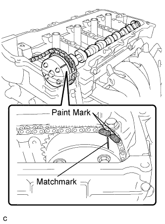
Hold up the chain and align the matchmark and the paint mark and install the camshaft.
 |
| 5. INSTALL NO. 2 CAMSHAFT |
Make sure that the valve rocker arm is installed as shown in the illustration.
|
Clean the camshaft journals.
Apply a light coat of engine oil to the camshaft journals, camshaft housings and bearing caps.
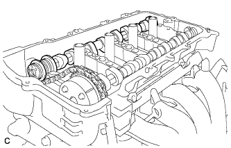
Install the No. 2 camshaft to the camshaft housing.
 |
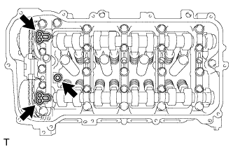
| 6. INSTALL CAMSHAFT BEARING CAP |
Check the marks and numbers on the camshaft bearing caps, and then remove the service bolts and spacers in the order shown in the illustration. Immediately after removing the service bolts and spacers in the location for bearing caps, install the bearing caps with the bolts in the order shown in the illustration.

Text in Illustration *1 Service Bolt and Spacer (used to temporarily secure the camshaft housing) *2 Knock Pin *3 Paint Mark *4 Matchmark *a The removal order of the bolts and spacers for temporarily tightening the camshaft housing *b The installation order of the parts - Torque:
- 27 N*m{275 kgf*cm, 20 ft.*lbf}
- NOTICE:
- If the bolts are loosened all at once, FIPG on the camshaft housing and cylinder head may peel off, resulting in oil oozing. Therefore, be sure to remove the service bolt and spacer from one bearing cap at a time.
- HINT:
- Make sure that the orientation of the knock pin and matchmark on the camshaft is as shown in the illustration.
Tighten the 10 bolts in the order shown in the illustration.
- Torque:
- 16 N*m{163 kgf*cm, 12 ft.*lbf}
 |
Check the torque of each bolt again.
| 7. INSTALL CAMSHAFT TIMING EXHAUST GEAR ASSEMBLY |
Hold the hexagonal portion of the intake camshaft with a wrench and turn it slightly counterclockwise to release the chain.
 |
Install the bolt to the camshaft timing exhaust gear assembly.
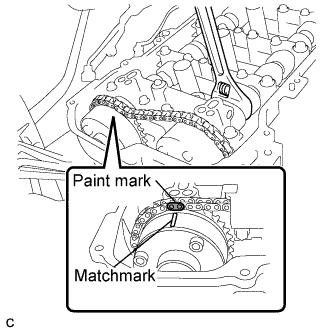
Align the paint mark with the matchmark to install the chain.
- NOTICE:
- Do not turn the intake camshaft more than necessary.
- Do not install the camshaft timing exhaust gear to the camshaft at this time. Make sure to only install the chain to the camshaft timing exhaust gear.
Put the camshaft timing exhaust gear and camshaft together by aligning the key groove and knock pin.
- NOTICE:
- If the straight pin cannot be aligned with the pin hole, hold the hexagonal portion of the No. 2 camshaft with a wrench and turn it slightly to install the gear.
- Do not turn the No. 2 camshaft more than necessary.
- Do not forcefully push in the camshaft timing exhaust gear assembly. This may cause the camshaft knock pin tip to damage the installation surface of the camshaft timing exhaust gear assembly.
 |
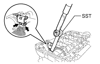
Using SST and a wrench, hold the hexagonal portion of the No. 2 camshaft and install the camshaft timing exhaust gear assembly to the No. 2 camshaft.
- SST
- 09249-37010
- Torque:
- without SST:
- 54 N*m{551 kgf*cm, 40 ft.*lbf}
- with SST:
- 39 N*m{397 kgf*cm, 29 ft.*lbf}
- NOTICE:
- The "with SST" torque value can be obtained by using a torque wrench with a fulcrum length of 260 mm (10.24 in.) and SST of 100 mm (3.94 in.) (COROLLA_ZRE142 RM000000UYX0ETX.html).
- This torque value is effective when SST is parallel to the torque wrench.
 |
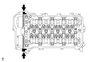
| 8. INSTALL NO. 2 CHAIN VIBRATION DAMPER |
Using SST, install the No. 2 chain vibration damper with the 2 bolts.
- SST
- 09961-00950
- Torque:
- without SST:
- 10 N*m{102 kgf*cm, 7 ft.*lbf}
- with SST:
- 5.5 N*m{56 kgf*cm, 48 in.*lbf}
- NOTICE:
- The "with SST" torque value can be obtained by using a torque wrench with a fulcrum length of 180 mm (7.09 in.) and SST of 150 mm (5.91 in.) (COROLLA_ZRE142 RM000000UYX0ETX.html).
- This torque value is effective when SST is parallel to the torque wrench.
 |
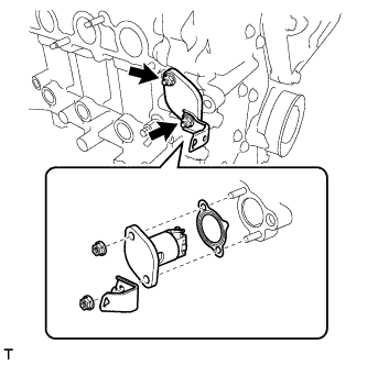
| 9. INSTALL NO. 1 CHAIN TENSIONER ASSEMBLY |
Release the ratchet pawl, then fully push in the plunger and engage the hook to the pin so that the plunger is in the position shown in the illustration.
- NOTICE:
- Make sure that the cam engages the first tooth of the plunger to allow the hook to pass over the pin.
 |
Install a new gasket, bracket and No. 1 chain tensioner with the 2 nuts.
- Torque:
- 12 N*m{122 kgf*cm, 9 ft.*lbf}
- NOTICE:
- If the hook releases the plunger while the chain tensioner is being installed, engage the hook again.
 |
Turn the crankshaft counterclockwise, then disconnect the hook from plunger knock pin.
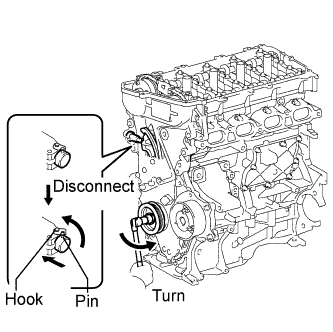 |
Turn the crankshaft clockwise, then check that the plunger is extended.
 |
| 10. SET NO. 1 CYLINDER TO TDC / COMPRESSION |
Turn the crankshaft pulley until its timing notch (groove) and the timing mark "0" of the timing chain cover are aligned.
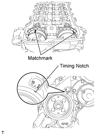 |
Check that each matchmark of the camshaft timing gear and camshaft timing exhaust gear are aligned with each matchmark located as shown in the illustration. If not, turn the crankshaft 1 revolution (360°) to align the timing marks as shown in the illustration.
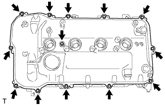
| 11. INSTALL CYLINDER HEAD COVER SUB-ASSEMBLY |
Install a new gasket to the cylinder head cover.
- NOTICE:
- Remove any oil from the contact surfaces.
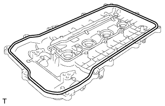 |
Install 3 new gaskets to the No. 1 camshaft bearing cap.
 |
Apply seal packing as shown the illustration.
- Seal packing:
- Toyota Genuine Seal Packing Black, Three Bond 1207B or equivalent
- NOTICE:
- Remove any oil from the contact surfaces.
- Install the cylinder head cover within 3 minutes and tighten the bolts within 15 minutes after applying seal packing.
- Do not start the engine for at least 2 hours after the installation.
 |
Install the cylinder head cover with a new seal washer and the 13 bolts.
- Torque:
- 10 N*m{102 kgf*cm, 7 ft.*lbf}
 |
| 12. INSTALL AIR TUBE |
Install the air tube assembly with the 2 bolts.
- Torque:
- 10 N*m{102 kgf*cm, 7 ft.*lbf}
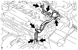 |
Connect the 4 hoses.
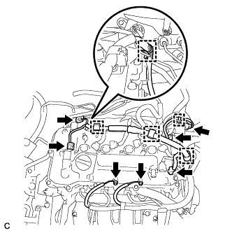
| 13. CONNECT ENGINE WIRE |
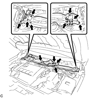
Connect the 5 connectors and install the wire harness with the 2 bolts and 5 clamps.
- Torque:
- 8.4 N*m{86 kgf*cm, 74 in.*lbf}
 |
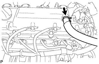
| 14. CONNECT NO. 2 VENTILATION HOSE |
Connect the No. 2 ventilation hose.
 |
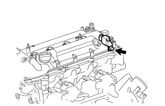
| 15. INSTALL RADIO SETTING CONDENSER |
Install the radio setting condenser with the bolt.
- Torque:
- 10 N*m{102 kgf*cm, 7 ft.*lbf}
 |
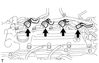
| 16. INSTALL IGNITION COIL ASSEMBLY |
Install the 4 ignition coils with the 4 bolts.
- Torque:
- 10 N*m{102 kgf*cm, 7 ft.*lbf}
- NOTICE:
- When installing each ignition coil, do not damage the plug cap on the engine head cover opening or the upper edge of the spark plug tube.
 |
Connect the 4 ignition coil connectors.
 |
| 17. INSPECT FOR ENGINE OIL LEAK |
| 18. INSTALL NO. 2 CYLINDER HEAD COVER |
Engage the 4 clips to install the No. 2 cylinder head cover.
- NOTICE:
- Be sure to engage the clips securely.
- Do not apply excessive force or do not hit the cover to engage the clips. This may cause the cover to break.
 |
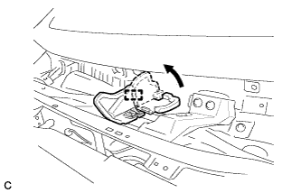
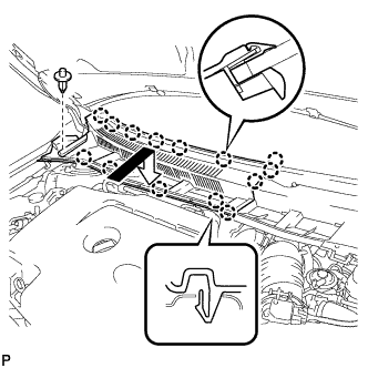
| 19. INSTALL OUTER COWL TOP PANEL (for TMC Made) |
Install the outer cowl top panel with the 12 bolts.
- Torque:
- 8.8 N*m{90 kgf*cm, 78 in.*lbf}
 |
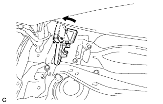
Engage the clamp.
Bend the water guard plate RH as shown in the illustration and engage the clamp.
 |
| 20. INSTALL OUTER COWL TOP PANEL (except TMC Made) |
Install the outer cowl top panel with the 12 bolts.
- Torque:
- 8.8 N*m{90 kgf*cm, 78 in.*lbf}
 |
Engage the clamp.
Bend the water guard plate RH as shown in the illustration, and engage the clamp.
|
Bend the No. 1 heater air duct splash shield seal as shown in the illustration, and engage the clamp.
 |
| 21. INSTALL WINDSHIELD WIPER MOTOR AND LINK ASSEMBLY |
Install the windshield wiper motor and link assembly with the 2 bolts.
- Torque:
- 5.5 N*m{56 kgf*cm, 49 in.*lbf}
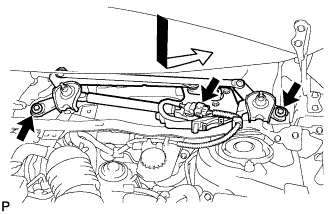 |
Connect the connector.
| 22. INSTALL COWL TOP VENTILATOR LOUVER LH |
Engage the clip and 8 claws to install the cowl top ventilator louver LH.
 |
| 23. INSTALL CENTER NO. 1 COWL TOP VENTILATOR LOUVER |
Engage the clip and 14 claws to install the center No. 1 cowl top ventilator louver.
 |
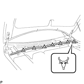
| 24. INSTALL HOOD TO COWL TOP SEAL |
Engage the 7 clips to install the hood to cowl top seal.
 |
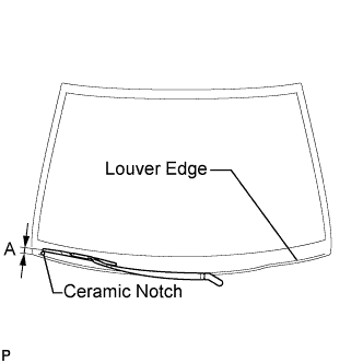
| 25. INSTALL FRONT WIPER ARM AND BLADE ASSEMBLY RH |
Operate the wiper and stop the windshield wiper motor at the automatic stop position.
Clean the wiper arm serrations.
 |
When reinstalling:
Clean the wiper pivot serrations with a wire brush.
Install the front wiper arm and blade assembly RH with the nut to the position shown in the illustration.
- Torque:
- 26 N*m{265 kgf*cm, 19 ft.*lbf}
- HINT:
- Hold the arm hinge by hand while fastening the nut.
Area Measurement A 27.5 to 42.5 mm (1.08 to 1.67 in.)
 |
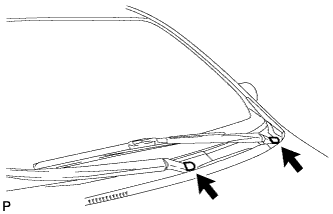
| 26. INSTALL FRONT WIPER ARM AND BLADE ASSEMBLY LH |
Operate the front wipers and stop the windshield wiper motor at the automatic stop position.
Clean the wiper arm serrations.
|
When reinstalling:
Clean the wiper pivot serrations with a wire brush.
Install the front wiper arm and blade assembly LH with the nut to the position shown in the illustration.
- Torque:
- 26 N*m{265 kgf*cm, 19 ft.*lbf}
- HINT:
- Hold the arm hinge by hand while fastening the nut.
Area Measurement A 31.5 to 46.5 mm (1.24 to 1.83 in.)
 |
Operate the front wipers while spraying washer fluid on the windshield glass. Make sure that the front wipers function properly and the wipers do not come into contact with the vehicle body.
| 27. INSTALL FRONT WIPER ARM HEAD CAP |
Install the 2 front wiper arm head caps.
 |
| 28. INSPECT IGNITION TIMING |
When using the Techstream:
Warm up and stop the engine.
Connect the Techstream to the DLC3.
Turn the ignition switch to ON.
Enter Data List Mode on the Techstream.
- HINT:
- Refer to the Techstream operator's manual for further details.
Inspect the ignition timing at idle.
- Ignition timing:
- 8 to 12 degrees BTDC
- NOTICE:
- Turn all the electrical systems and the A/C off.
- Inspect the ignition timing with the cooling fans off.
- When checking the ignition timing, shift the transmission to the neutral position.
Enter the following menus : TC (TE1) / OFF.
Turn the ignition switch off.
Disconnect the Techstream from the DLC3.
When not using the Techstream:
Remove the No. 2 cylinder head cover (COROLLA_ZRE142 RM000002WH607RX.html).
| 29. INSPECT ENGINE IDLING SPEED |
Warm up and stop the engine.
Connect the Techstream to the DLC3.
Turn the ignition switch to ON.
Enter Data List Mode on the Techstream.
- HINT:
- Refer to the Techstream operator's manual for further details.
Inspect the engine idle speed.
- Idle speed:
- 600 to 700 rpm
- NOTICE:
- Turn all the electrical systems and the A/C off.
- Inspect the idle speed with the cooling fans off.
- When checking the idle speed, shift the transmission to either neutral or park.
Turn the ignition switch off.
Disconnect the Techstream from the DLC3.