INSTALL NO. 2 INSTRUMENT PANEL UNDER COVER SUB-ASSEMBLY (w/ Instrument Panel Under Cover)
INSTALL AIR CONDITIONING PANEL ASSEMBLY (for Manual Air Conditioning System)
INSTALL AIR CONDITIONING CONTROL ASSEMBLY (for Automatic Air Conditioning System)
INSTALL CENTER NO. 1 INSTRUMENT CLUSTER FINISH PANEL ASSEMBLY (for Manual Transaxle)
INSTALL CENTER NO. 1 INSTRUMENT CLUSTER FINISH PANEL ASSEMBLY (for Automatic Transaxle)
INSTALL SHIFT LEVER KNOB SUB-ASSEMBLY (for Manual Transaxle)
INSTALL SHIFT LEVER KNOB SUB-ASSEMBLY (for Automatic Transaxle)
INSTALL RADIO RECEIVER WITH BRACKET (for Radio Receiver Type without USB Audio System)
INSTALL RADIO RECEIVER WITH BRACKET (for Radio Receiver Type with USB Audio System)
INSTALL RADIO AND DISPLAY RECEIVER WITH BRACKET (for Radio and Display Type)
INSTALL NAVIGATION RECEIVER WITH BRACKET (for Navigation Receiver Type)
INSTALL CENTER INSTRUMENT CLUSTER FINISH PANEL SUB-ASSEMBLY (w/ USB Audio System)
Lower Instrument Panel -- Installation |
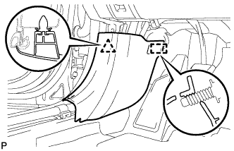
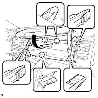
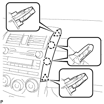
| 1. INSTALL LOWER INSTRUMENT PANEL SUB-ASSEMBLY |
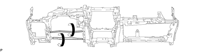
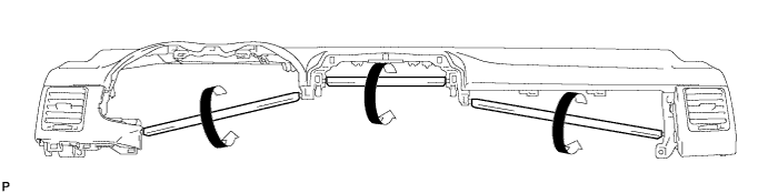
When using a new lower instrument panel sub-assembly:
Immediately before installing the lower instrument panel sub-assembly, twist and cut off the portions shown in the illustration (joints for moulding).
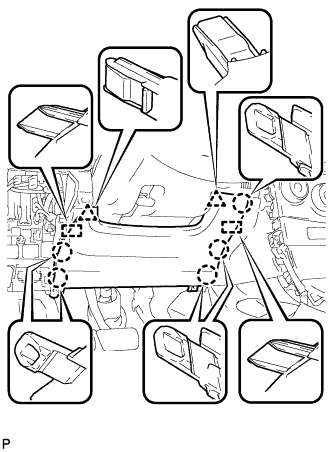
Install the lower instrument panel sub-assembly and engage the 2 claws.
- NOTICE:
- Do not allow the wire harness to get caught in the claws.
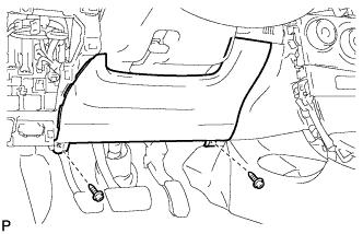
Install the screw <F>.
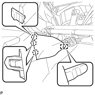
Install the 2 bolts <C>.
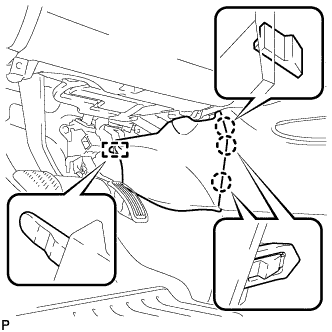
Install the 8 screws <D> or <E>.

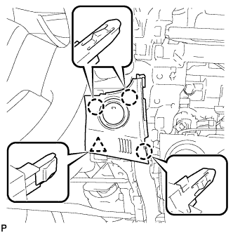
Engage each clamp.
Install the 3 screws <F>.
Connect each connector.

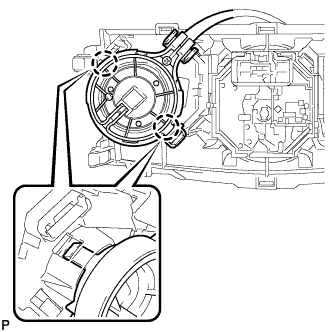
Engage the 3 claws and install the hood lock control cable assembly.
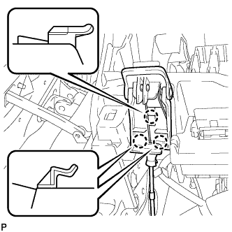 |
Engage the 2 claws and install the DLC3.
 |
| 2. INSTALL NO. 2 ANTENNA CORD SUB-ASSEMBLY |
Engage the 5 clamps and install the No. 2 antenna cord sub-assembly.
for 3 Connector Type:
Connect the connector.
Install the bolt.
- Torque:
- 8.4 N*m{86 kgf*cm, 74 in.*lbf}
Engage the clamp.
Connect the connector.
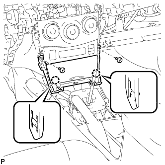
| 3. INSTALL CONSOLE BOX ASSEMBLY (for Automatic Transaxle) |
Install the 2 screws.
Install the console box assembly with the 2 bolts and 2 screws.
| 4. INSTALL CONSOLE BOX ASSEMBLY (for Manual Transaxle) |
Install the 2 screws.
Install the console box assembly with the 2 bolts.
| 5. INSTALL CONSOLE BOX CARPET |
Install the console box carpet.
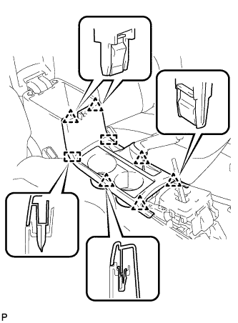
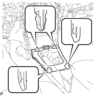
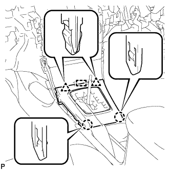
| 6. INSTALL UPPER CONSOLE PANEL SUB-ASSEMBLY |
Engage the 6 clips and 2 guides to install the upper console panel sub-assembly.
 |
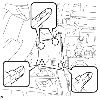
| 7. INSTALL NO. 1 SWITCH HOLE BASE (w/o Smart Key System) |
Engage the 3 claws and clip, and install the No. 1 switch hole base.
 |
| 8. INSTALL NO. 1 SWITCH HOLE BASE (w/ Smart Key System) |
Connect the connector.
 |
Engage the 3 claws and install the No. 1 switch hole base.
| 9. INSTALL LOWER INSTRUMENT PANEL FINISH PANEL SUB-ASSEMBLY |
Engage the 5 claws, 2 clips and 2 guides.
 |
Install the lower instrument panel finish panel sub-assembly with the 2 screws <B>.
 |
| 10. INSTALL FRONT NO. 1 CONSOLE BOX INSERT |
Engage the guide.
 |
Engage the 3 claws and install the front No. 1 console box insert.
| 11. INSTALL COWL SIDE TRIM BOARD LH |
Engage the guide and clip, and install the cowl side trim board LH.
 |
| 12. INSTALL FRONT DOOR SCUFF PLATE LH |
Engage the 8 claws and install the front door scuff plate LH.
 |
| 13. INSTALL FRONT NO. 2 CONSOLE BOX INSERT |
Engage the guide.
 |
Engage the 3 claws and install the front No. 2 console box insert.
| 14. INSTALL NO. 2 INSTRUMENT PANEL UNDER COVER SUB-ASSEMBLY (w/ Instrument Panel Under Cover) |
Engage the guide.
 |
Engage the 3 claws and install the No. 2 instrument panel under cover sub-assembly.
| 15. INSTALL COWL SIDE TRIM BOARD RH |
- HINT:
- Use the same procedure for the RH side and LH side.
| 16. INSTALL FRONT DOOR SCUFF PLATE RH |
- HINT:
- Use the same procedure for the RH side and LH side.
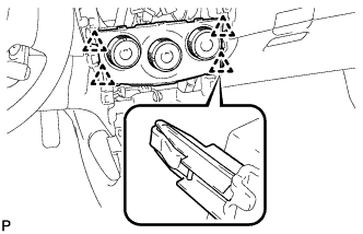
| 17. INSTALL AIR CONDITIONING PANEL ASSEMBLY (for Manual Air Conditioning System) |
Engage the 2 claws and the airmix damper control cable sub-assembly.
 |
Engage the 2 claws and the No. 2 heater control cable sub-assembly.
 |
Connect each connector.
Engage the 4 clips and install the air conditioning panel assembly.
 |
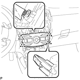
| 18. INSTALL AIR CONDITIONING CONTROL ASSEMBLY (for Automatic Air Conditioning System) |
Connect the connector.
Engage the 4 clips and install the air conditioning control assembly.
 |
| 19. INSTALL INSTRUMENT PANEL HOLE COVER |
Connect the each connector.
 |
Engage the 4 claws and install the instrument panel hole cover.
| 20. INSTALL INSTRUMENT PANEL BOX ASSEMBLY |
Connect the connector.
Engage the 2 claws.
 |
Install the instrument panel box assembly with the 2 screws <B>.
| 21. INSTALL CENTER NO. 1 INSTRUMENT CLUSTER FINISH PANEL ASSEMBLY (for Manual Transaxle) |
Engage the guide.
 |
Engage the 2 claws and 2 clips, and install the center No.1 instrument cluster finish panel assembly.
| 22. INSTALL CENTER NO. 1 INSTRUMENT CLUSTER FINISH PANEL ASSEMBLY (for Automatic Transaxle) |
Engage the guide.
 |
Engage the 2 claws and 2 clips, and install the center No.1 instrument cluster finish panel assembly.
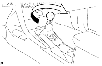
| 23. INSTALL SHIFT LEVER KNOB SUB-ASSEMBLY (for Manual Transaxle) |
Turn the shift lever knob clockwise and install the shift lever knob sub-assembly.
 |
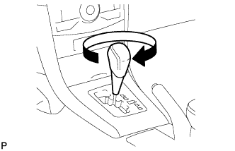
| 24. INSTALL SHIFT LEVER KNOB SUB-ASSEMBLY (for Automatic Transaxle) |
Turn the shift lever knob clockwise and install the shift lever knob sub-assembly.
 |
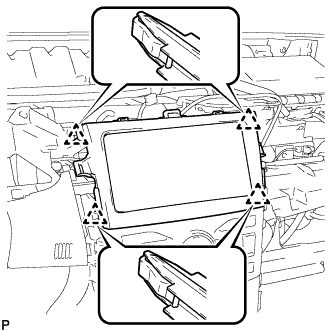
| 25. INSTALL RADIO RECEIVER WITH BRACKET (for Radio Receiver Type without USB Audio System) |
Connect each connector.
Engage the 4 clips.
- CAUTION:
- When installing the radio receiver with bracket, check that the wire harness and No. 2 antenna cord sub-assembly are not caught between the radio receiver with bracket and the instrument panel reinforcement assembly. Failure to do so may cause a short circuit.
Install the radio receiver with bracket with the 4 bolts.
| 26. INSTALL RADIO RECEIVER WITH BRACKET (for Radio Receiver Type with USB Audio System) |
Connect each connector.
Install the radio receiver with bracket with the 4 bolts.
- CAUTION:
- When installing the radio receiver with bracket, check that the wire harness and No. 2 antenna cord sub-assembly are not caught between the radio receiver with bracket and the instrument panel reinforcement assembly. Failure to do so may cause a short circuit.
| 27. INSTALL RADIO AND DISPLAY RECEIVER WITH BRACKET (for Radio and Display Type) |
Connect each connector.
Install the radio and display receiver with bracket with the 4 bolts.
- CAUTION:
- When installing the radio and display receiver with bracket, check that the wire harness and No. 2 antenna cord sub-assembly are not caught between the radio and display receiver with bracket and the instrument panel reinforcement assembly. Failure to do so may cause a short circuit.
| 28. INSTALL NAVIGATION RECEIVER WITH BRACKET (for Navigation Receiver Type) |
Connect each connector.
Engage the 4 clips.
- CAUTION:
- When installing the navigation receiver with bracket, check that the wire harness and No. 2 antenna cord sub-assembly are not caught between the navigation receiver with bracket and the instrument panel reinforcement assembly. Failure to do so may cause a short circuit.
Install the navigation receiver with bracket with the 4 bolts.
| 29. INSTALL CENTER INSTRUMENT CLUSTER FINISH PANEL SUB-ASSEMBLY (w/ USB Audio System) |
Engage the 4 clips to install the center instrument cluster finish panel sub-assembly.
 |
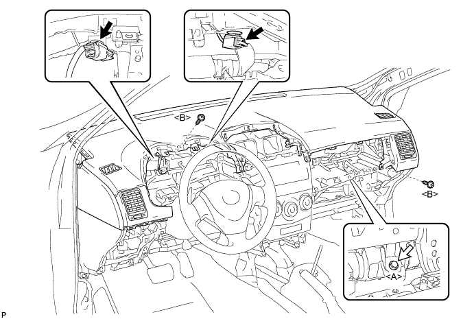
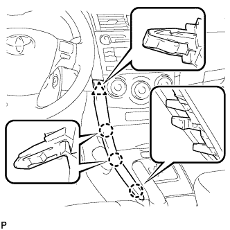
| 30. INSTALL UPPER INSTRUMENT PANEL SUB-ASSEMBLY |
When using a new upper instrument panel sub-assembly:
Immediately before installing the upper instrument panel sub-assembly, twist and cut off the portions shown in the illustration (joints for moulding).
Install the upper instrument panel sub-assembly and engage the 5 claws.
- NOTICE:
- When installing the upper instrument panel sub-assembly, be careful not to damage it or the steering wheel assembly.
- Do not allow the wire harness to get caught in the claws.

Engage the 5 clips and 4 guides.

Install the 2 screws <B>.
Install the passenger airbag bolt <A>.
- Torque:
- 20 N*m{204 kgf*cm, 15 ft.*lbf}
Connect each connector.
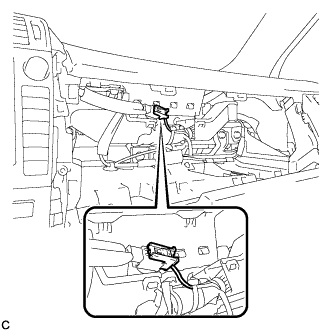
| 31. CONNECT INSTRUMENT PANEL WIRE ASSEMBLY |
Check that the ignition switch is off.
Check that the cable is disconnected from the negative (-) battery terminal.
- CAUTION:
- Wait at least 90 seconds after disconnecting the cable from the negative (-) battery terminal to disable the SRS system.
Connect the connector.
- NOTICE:
- When connecting the airbag connector, take care not to damage the airbag wire harness.
 |
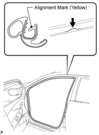
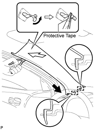
| 32. CONNECT FRONT DOOR OPENING TRIM WEATHERSTRIP LH |
Align the alignment mark (yellow) on the weatherstrip and the protruding portion on the body indicated by the arrow in the illustration, and install the front door opening trim weatherstrip LH.
- NOTICE:
- After installation, check that the corners fit correctly.
 |
| 33. INSTALL LOWER INSTRUMENT PANEL FINISH PANEL ASSEMBLY |
Connect each connector.
Engage the 6 claws and 3 clips to install the lower instrument panel finish panel assembly.
 |
| 34. CONNECT FRONT DOOR OPENING TRIM WEATHERSTRIP RH |
- HINT:
- Use the same procedure for the RH side and LH side.
| 35. INSTALL NO. 1 INSTRUMENT PANEL BOX DOOR SUB-ASSEMBLY |
Engage the 3 claws and 4 clips.
 |
Install the No. 1 instrument panel box door sub-assembly with the screw <B>.
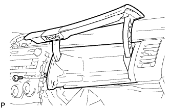 |
| 36. INSTALL GLOVE COMPARTMENT DOOR ASSEMBLY |
Insert the glove compartment door assembly horizontally and engage the 2 hinges.
- NOTICE:
- Engaging the hinges from the above will deform the hinges. Be sure to install the glove compartment door assembly horizontally.
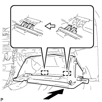 |
Bend portions (A) and (B) in the direction indicated by the arrows in the illustration to engage the 2 stoppers.
 |
Engage the claw, connect the glove compartment door stopper, and install the glove compartment door assembly.
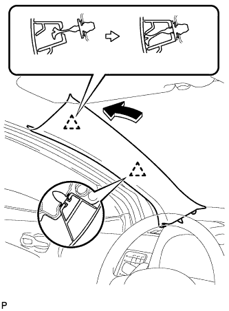
| 37. INSTALL FRONT PILLAR GARNISH LH |
Remove the protective cover.
 |
Make sure that the front pillar garnish clip is not damaged.
- NOTICE:
- If there is any damage, replace the garnish clip with a new one.
- When a garnish clip is being replaced, make sure to install it in the direction shown in the illustration.
 |
Engage the 2 guides.
Turn the end of the front pillar garnish clip 90° with needle-nosed pliers and install it to the front pillar garnish LH.
- HINT:
- Tape the tips of the needle-nosed pliers before use.
Engage the 2 clips to install the front pillar garnish LH.
 |
| 38. INSTALL FRONT PILLAR GARNISH RH |
- HINT:
- Use the same procedure as for the LH side.
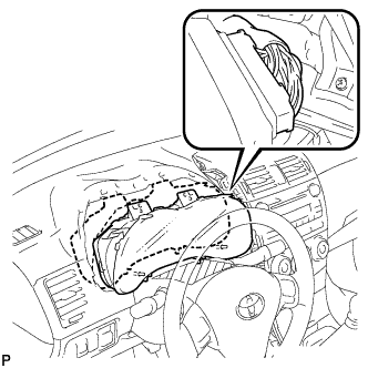
| 39. INSTALL COMBINATION METER ASSEMBLY |
Connect the connector and temporarily install the combination meter assembly.
- NOTICE:
- When installing the combination meter assembly, do not damage the upper instrument panel sub-assembly or combination meter assembly.
 |
Engage the 2 guides.
- NOTICE:
- When installing the combination meter assembly, be careful not to break the guide.
- When installing the combination meter assembly, insert the guides securely into the holes on the upper instrument panel sub-assembly.
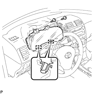 |
Install the combination meter assembly with the 2 screws.
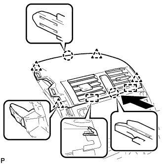
| 40. INSTALL INSTRUMENT CLUSTER FINISH PANEL ASSEMBLY |
Engage the guide, claw and 3 clips, and install the instrument cluster finish panel assembly.
 |
Remove the applied protective tape on the steering column cover.
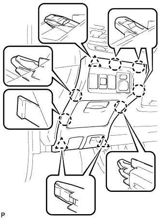
| 41. INSTALL CENTER INSTRUMENT PANEL REGISTER ASSEMBLY |
Connect each connector.
w/o Daytime Running Light:
Engage the clamp.
Engage the 2 guides, 2 claws and 4 clips, and install the center instrument panel register assembly.
 |
| 42. INSTALL INSTRUMENT PANEL FINISH PANEL END LH |
Engage the 2 claws and 2 clips, and then install the instrument panel finish panel end LH.
 |
| 43. INSTALL INSTRUMENT PANEL FINISH PANEL END RH |
Engage the 2 claws and 2 clips, and then install the instrument panel finish panel end RH.
 |
| 44. INSTALL LOWER INSTRUMENT PANEL FINISH PANEL LH |
Engage the 3 claws and clip, and then install the lower instrument panel finish panel LH.
 |
| 45. INSTALL LOWER INSTRUMENT PANEL FINISH PANEL RH |
Engage the 3 claws and clip, and then install the lower instrument panel finish panel RH.
 |
| 46. CONNECT CABLE TO NEGATIVE BATTERY TERMINAL |
| 47. INSPECT SRS WARNING LIGHT |