Clutch Pedal -- Installation |
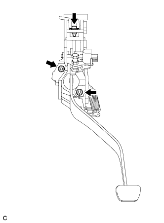
| 1. INSTALL CLUTCH PEDAL SWITCH ASSEMBLY |
Install the clutch pedal switch assembly to the clutch pedal support sub-assembly with the nut.
- Torque:
- 16 N*m{160 kgf*cm, 12 ft.*lbf}
| 2. INSTALL CLUTCH SWITCH ASSEMBLY (w/ Cruise Control System) |
Install the clutch switch assembly to the clutch pedal support sub-assembly with the nut.
- Torque:
- 16 N*m{160 kgf*cm, 12 ft.*lbf}
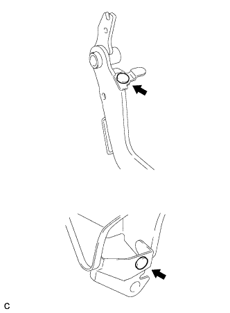
| 3. INSTALL CLUTCH MASTER CYLINDER PUSH ROD CLEVIS BUSHING |
Apply MP grease to the inside of a new clevis bushing.
 |
Install the clevis bushing to the clutch pedal sub-assembly.
- HINT:
- Install the clevis bushing from the right side of the vehicle.
| 4. INSTALL NO. 1 CLUTCH PEDAL CUSHION |
Install the 2 No. 1 clutch pedal cushions to the clutch pedal sub-assembly and clutch pedal support sub-assembly.
 |
| 5. INSTALL CLUTCH PEDAL BUSHING |
Apply MP grease to both sides and end surface of 2 new bushings.
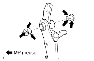 |
Install the 2 bushings to the clutch pedal.
| 6. INSTALL CLUTCH PEDAL PAD |
Install the clutch pedal pad to the clutch pedal sub-assembly.
| 7. INSTALL CLUTCH PEDAL SUB-ASSEMBLY |
Install the clutch pedal sub-assembly to the clutch pedal support sub-assembly with the bolt and nut.
- Torque:
- 37 N*m{375 kgf*cm, 27 ft.*lbf}
- HINT:
- Install the bolt from the right side of the vehicle.
 |
| 8. INSTALL TURN OVER SPRING SEAT COMPRESSION SPRING |
Apply MP grease to the sliding portion of the 2 turn over bushings.
 |
Install a 2 new turn over bushings to the clutch pedal sub-assembly and clutch pedal support sub-assembly.
Install the turn over spring.
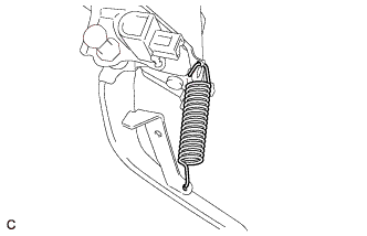
| 9. INSTALL CLUTCH PEDAL SPRING (for 2AZ-FE) |
Install the clutch pedal spring.
 |
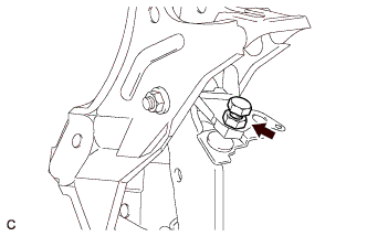
| 10. INSTALL CLUTCH PEDAL STOPPER BOLT |
Install the clutch pedal stopper bolt so that its end touches the clutch pedal cushion.
- HINT:
- Tighten the lock nut to the specified torque when adjusting the clutch pedal.
 |
| 11. INSTALL CLUTCH PEDAL SUPPORT SUB-ASSEMBLY |
Install the nut to the clutch pedal support sub-assembly.
 |
Install the clutch pedal support sub-assembly with the 2 nuts and bolt.
- Torque:
- Bolt:
- 24 N*m{241 kgf*cm, 17 ft.*lbf}
- Nut:
- 13 N*m{130 kgf*cm, 9 ft.*lbf}
 |
| 12. INSTALL CLUTCH MASTER CYLINDER PUSH ROD CLEVIS WITH HOLE PIN |
Connect the clevis to the clutch pedal sub-assembly with the hole pin.
- HINT:
- Install the hole pin from the right side of the vehicle.
 |
Install the clip to the hole pin.
| 13. CONNECT CONNECTORS |
Connect the clutch pedal switch connector.
Connect the clutch switch assembly connector.
| 14. INSTALL MAIN BODY ECU (INSTRUMENT PANEL JUNCTION BLOCK) |
Install the main body ECU with the 3 screws.
 |
| 15. INSPECT CLUTCH PEDAL SWITCH ASSEMBLY |
Check that the engine does not start when the clutch pedal is released.
 |
Check that the engine starts when the clutch pedal is fully depressed.
If necessary, inspect and replace the clutch pedal switch assembly.
| 16. INSTALL UPPER INSTRUMENT PANEL SUB-ASSEMBLY |
| 17. CONNECT CABLE TO NEGATIVE BATTERY TERMINAL |
| 18. INSPECT SRS WARNING LIGHT |