Navigation System Vehicle Speed Signal Circuit Between Radio Receiver And Extension Module
DESCRIPTION
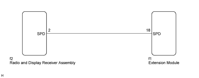
WIRING DIAGRAM
INSPECTION PROCEDURE
CHECK HARNESS AND CONNECTOR (RADIO AND DISPLAY RECEIVER ASSEMBLY - EXTENSION MODULE)
NAVIGATION SYSTEM - Vehicle Speed Signal Circuit between Radio Receiver and Extension Module |
DESCRIPTION
The extension module receives a vehicle speed signal from the radio and display receiver assembly and information from the navigation antenna, and then adjusts vehicle position.
WIRING DIAGRAM
INSPECTION PROCEDURE
| 1.CHECK HARNESS AND CONNECTOR (RADIO AND DISPLAY RECEIVER ASSEMBLY - EXTENSION MODULE) |
Disconnect the radio and display receiver assembly connector.
Disconnect the extension module connector.
Measure the resistance according to the value(s) in the table below.
- Standard Resistance:
Tester Connection
| Condition
| Specified Condition
|
f2-2 (SPD) - f1-18 (SPD)
| Always
| Below 1 Ω
|
f2-2 (SPD) - Body ground
| Always
| 10 kΩ or higher
|
| | REPAIR OR REPLACE HARNESS OR CONNECTOR |
|
|