Transmission Control Cable -- Installation |
| 1. INSTALL TRANSMISSION CONTROL CABLE ASSEMBLY |
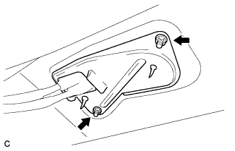
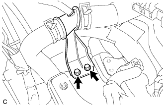
Install the transmission control cable assembly with the 2 nuts.
- Torque:
- 5.0 N*m{51 kgf*cm, 44 in.*lbf}
 |
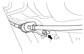
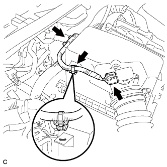
Install the transmission control cable assembly with the nut.
- Torque:
- 5.0 N*m{51 kgf*cm, 44 in.*lbf}
 |
Install the 2 transmission control cables to the control cable bracket with 2 new clips*1.
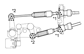 |
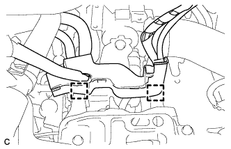
Install the 2 transmission control cables to the transaxle with the 2 clips*2.
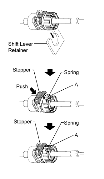
Rotate the transmission control cable nut counterclockwise approximately 180° and, while holding the nut in that position, press in the stopper until it makes 2 "click" sounds.
 |
Install the outer part of the transmission control cable to the shift lever retainer, check that the position of the spring is the same as A shown in the illustration, and push in the stopper.
- HINT:
- If the stopper cannot be pushed in, slightly rotate the nut clockwise and then push in the stopper.
 |
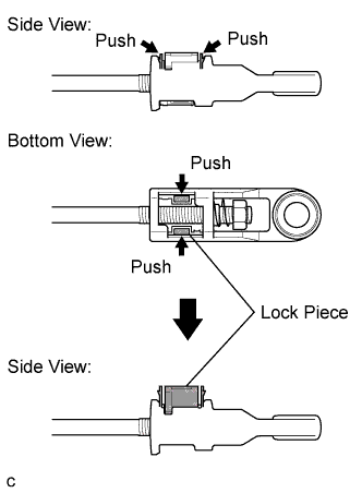
Push the two claws together at the top of the transmission control cable lock piece. While holding the two claws together, push the two lugs on the bottom of the lock piece toward each other and upward to pull out the lock piece.
 |
Install the transmission control shift cable to the shift lever assembly.
 |
Install the control select cable to the shift lever assembly.
- NOTICE:
- Make sure to adjust the length at the neutral shift position.
- Make sure that the lock piece is protruding from the adjuster case.
Install the clip to the shift lever assembly.
Press in and lock the lock piece to the adjuster case.
- NOTICE:
- Securely press in the lock piece until the lock engages.
| 2. ADJUST TRANSMISSION CONTROL SELECT CABLE |
Remove the console box assembly (COROLLA_ZRE142 RM000002XV501QX.html).
Remove the clip and disconnect the control select cable from the shift lever assembly.
 |
Push the two claws together at the top of the transmission control cable lock piece. While holding the two claws together, push the two lugs on the bottom of the lock piece toward each other and upward to pull out the lock piece.
|
Install the transmission control shift cable to the shift lever assembly.
|
Install the control select cable to the shift lever assembly.
- NOTICE:
- Make sure to adjust the length at the neutral shift position.
- Make sure that the lock piece is protruding from the adjuster case.
Install the clip to the shift lever assembly.
Press in and lock the lock piece to the adjuster case.
- NOTICE:
- Securely press in the lock piece until the lock engages.
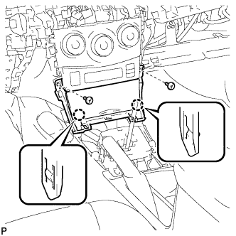
| 3. INSTALL CONSOLE BOX ASSEMBLY |
Install the 2 screws.
Install the console box assembly with the 2 bolts.
| 4. INSTALL CONSOLE BOX CARPET |
Install the console box carpet.
| 5. INSTALL UPPER CONSOLE PANEL SUB-ASSEMBLY |
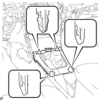
Engage the 6 clips and 2 guides to install the upper console panel sub-assembly.
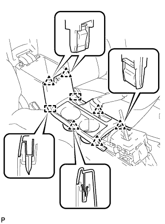 |
| 6. INSTALL FRONT NO. 1 CONSOLE BOX INSERT |
Engage the guide.
 |
Engage the 3 claws and install the front No. 1 console box insert.
| 7. INSTALL FRONT NO. 2 CONSOLE BOX INSERT |
Engage the guide.
 |
Engage the 3 claws and install the front No. 2 console box insert.
| 8. INSTALL INSTRUMENT PANEL BOX ASSEMBLY |
Connect the connector.
Engage the 2 claws.
 |
Install the instrument panel box assembly with the 2 screws <B>.
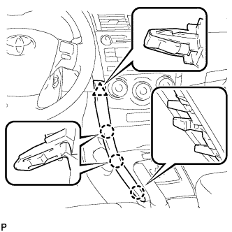
| 9. INSTALL CENTER NO. 1 INSTRUMENT CLUSTER FINISH PANEL ASSEMBLY |
Engage the guide.
 |
Engage the 2 claws and 2 clips, and install the center No.1 instrument cluster finish panel assembly.
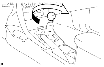
| 10. INSTALL SHIFT LEVER KNOB SUB-ASSEMBLY |
Turn the shift lever knob clockwise and install the shift lever knob sub-assembly.
 |
| 11. INSTALL LOWER INSTRUMENT PANEL FINISH PANEL LH |
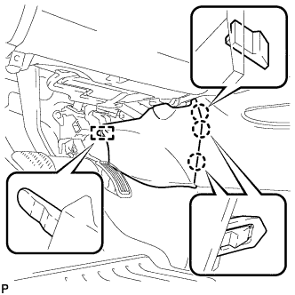
Engage the 3 claws and clip, and then install the lower instrument panel finish panel LH.
 |
| 12. INSTALL LOWER INSTRUMENT PANEL FINISH PANEL RH |
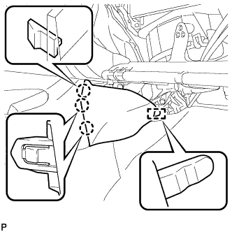
Engage the 3 claws and clip, and then install the lower instrument panel finish panel RH.
 |
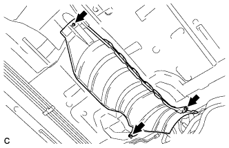
| 13. INSTALL FRONT NO. 1 FLOOR HEAT INSULATOR |
Install the No. 1 front floor heat insulator with the 3 nuts.
- Torque:
- 5.5 N*m{56 kgf*cm, 49 in.*lbf}
 |
| 14. INSTALL FRONT EXHAUST PIPE ASSEMBLY |
Using a vernier caliper, measure the free length of the compression springs.
Minimum (front) 41.5 mm (1.64 in.) Minimum (rear) 38.5 mm (1.52 in.) - HINT:
- If the free length is less than the minimum, replace the compression spring.
 |
Fully insert 2 new gaskets to the exhaust manifold and front exhaust pipe assembly.
Using a plastic hammer and wooden block, tap in each gasket until its surface is flush with the exhaust manifold and front exhaust pipe assembly.
Text in Illustration *1 Exhaust Manifold and Front Exhaust Pipe Assembly *2 Gasket *3 Wooden Block - NOTICE:
- Be careful with the installation direction of the gaskets.
- Do not reuse the gaskets.
- Do not damage the gaskets.
- Do not push in the gaskets by using the exhaust pipe when connecting it.
 |
Connect the front exhaust pipe assembly to the 2 exhaust pipe supports.
Install the front exhaust pipe assembly with the 4 bolts and 4 compression springs.
- Torque:
- 43 N*m{440 kgf*cm, 32 ft.*lbf}
Connect the heated oxygen sensor connector.
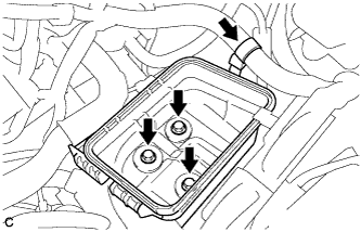
| 15. INSTALL AIR CLEANER CASE |
Install the air cleaner case with the 3 bolts.
- Torque:
- 7.0 N*m{71 kgf*cm, 62 in.*lbf}
 |
Install the wire harness clamp to the air cleaner case.
Install the air cleaner filter element.
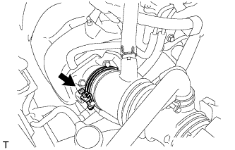
| 16. INSTALL AIR CLEANER CAP SUB-ASSEMBLY |
Install the air cleaner cap sub-assembly with hose with the 2 clamps.
Tighten the hose clamp to the specified torque.
- Torque:
- 2.0 N*m{20 kgf*cm, 18 in.*lbf}
 |
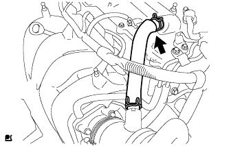
Connect the ventilation hose.
 |
Connect the 2 wire harness clamps and mass air flow meter connector.
 |
| 17. INSTALL BATTERY CARRIER |
Install the battery carrier with the 4 bolts.
- Torque:
- 13 N*m{130 kgf*cm, 9 ft.*lbf}
Connect the radiator pipe with the 2 bolts.
- Torque:
- 8.8 N*m{90 kgf*cm, 78 in.*lbf}
 |
Connect the 2 wire harness clamps.
 |
| 18. INSTALL BATTERY TRAY |
| 19. INSTALL BATTERY |
Install the battery clamp with the bolt and nut.
- Torque:
- for bolt:
- 6.5 N*m{66 kgf*cm, 58 in.*lbf}
- for nut:
- 3.5 N*m{36 kgf*cm, 31 in.*lbf}
Connect the battery cables.
- Torque:
- 5.4 N*m{55 kgf*cm, 48 in.*lbf}
| 20. INSPECT FOR EXHAUST GAS LEAK |
| 21. INSTALL NO. 2 CYLINDER HEAD COVER |
Engage the 4 clips to install the No. 2 cylinder head cover.
- NOTICE:
- Be sure to engage the clips securely.
- Do not apply excessive force or do not hit the cover to engage the clips. This may cause the cover to break.
 |
| 22. CONNECT CABLE TO NEGATIVE BATTERY TERMINAL |
- NOTICE:
- When disconnecting the cable, some systems need to be initialized after the cable is reconnected (COROLLA_ZRE142 RM00000315Z05EX.html).