Lighting System Front Fog Light Circuit
DESCRIPTION
WIRING DIAGRAM
INSPECTION PROCEDURE
INSPECT FUSE (FR FOG)
INSPECT FRONT FOG LIGHT RELAY
CHECK HARNESS AND CONNECTOR (BATTERY - FRONT FOG LIGHT RELAY)
INSPECT HEADLIGHT DIMMER SWITCH ASSEMBLY
CHECK HARNESS AND CONNECTOR (FRONT FOG LIGHT RELAY - HEADLIGHT DIMMER SWITCH ASSEMBLY)
CHECK HARNESS AND CONNECTOR (HEADLIGHT DIMMER SWITCH ASSEMBLY - DAYTIME RUNNING LIGHT RELAY)
CHECK HARNESS AND CONNECTOR (FRONT FOG LIGHT RELAY - FOG LIGHT ASSEMBLY)
CHECK HARNESS AND CONNECTOR (FOG LIGHT ASSEMBLY - BODY GROUND)
LIGHTING SYSTEM - Front Fog Light Circuit |
DESCRIPTION
- When both of the following conditions are met, the front fog lights come on:
- The low beam headlights are turned on using either automatic light control or manual operation, and the high beam headlights are off.
- Front fog light switch is on.
WIRING DIAGRAM
INSPECTION PROCEDURE
Remove the FR FOG fuse from the instrument panel junction block.
Measure the resistance according to the value(s) in the table below.
- Standard Resistance:
Tester Connection
| Condition
| Specified Condition
|
FR FOG fuse
| Always
| Below 1 Ω
|
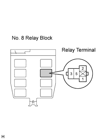
| 2.INSPECT FRONT FOG LIGHT RELAY |
Remove the front fog light relay.
Measure the resistance according to the value(s) in the table below.
- Standard Resistance:
Tester Connection
| Condition
| Specified Condition
|
3 - 5
| Voltage is not applied between terminals 1 and 2
| 10 kΩ or higher
|
3 - 5
| Voltage is applied between terminals 1 and 2
| Below 1 Ω
|
| | REPLACE FRONT FOG LIGHT RELAY |
|
|
| 3.CHECK HARNESS AND CONNECTOR (BATTERY - FRONT FOG LIGHT RELAY) |
for TMC Made
Install the FR FOG fuse.
Measure the voltage according to the value(s) in the table below.
- Standard Voltage:
Tester Connection
| Condition
| Specified Condition
|
2 - Body ground
| Always
| 11 to 14 V
|
5 - Body ground
| Always
| 11 to 14 V
|
except TMC Made
Install the FR FOG fuse.
Measure the voltage according to the value(s) in the table below.
- Standard Voltage:
Tester Connection
| Condition
| Specified Condition
|
2 - Body ground
| Always
| 11 to 14 V
|
5 - Body ground
| Always
| 11 to 14 V
|
| | REPAIR OR REPLACE HARNESS OR CONNECTOR |
|
|
| 4.INSPECT HEADLIGHT DIMMER SWITCH ASSEMBLY |
Remove the headlight dimmer switch assembly.
Measure the resistance according to the value(s) in the table below.
- Standard Resistance:
Tester Connection
| Condition
| Specified Condition
|
3 (LFG) - 4 (BFG)
| Fog light switch off
| 10 kΩ or higher
|
3 (LFG) - 4 (BFG)
| Fog light switch on
| Below 1 Ω
|
Reinstall the headlight dimmer switch assembly.
| 5.CHECK HARNESS AND CONNECTOR (FRONT FOG LIGHT RELAY - HEADLIGHT DIMMER SWITCH ASSEMBLY) |
for TMC Made
Disconnect the E8 headlight dimmer switch assembly connector.
Measure the resistance according to the value(s) in the table below.
- Standard Resistance:
Tester Connection
| Condition
| Specified Condition
|
Front fog light relay terminal 1 - E8-4 (BFG)
| Always
| Below 1 Ω
|
Front fog light relay terminal 1 - Body ground
| Always
| 10 kΩ or higher
|
except TMC Made
Disconnect the E8 headlight dimmer switch assembly connector.
Measure the resistance according to the value(s) in the table below.
- Standard Resistance:
Tester Connection
| Condition
| Specified Condition
|
Front fog light relay terminal 1 - E8-4 (BFG)
| Always
| Below 1 Ω
|
Front fog light relay terminal 1 - Body ground
| Always
| 10 kΩ or higher
|
| | REPAIR OR REPLACE HARNESS OR CONNECTOR |
|
|
| 6.CHECK HARNESS AND CONNECTOR (HEADLIGHT DIMMER SWITCH ASSEMBLY - DAYTIME RUNNING LIGHT RELAY) |
Disconnect the E91 daytime running light relay connector.
Measure the resistance according to the value(s) in the table below.
- Standard Resistance:
Tester Connection
| Condition
| Specified Condition
|
E8-3 (LFG) - E91-2 (FOG)
| Always
| Below 1 Ω
|
E8-3 (LFG) - Body ground
| Always
| 10 kΩ or higher
|
| | REPAIR OR REPLACE HARNESS OR CONNECTOR |
|
|
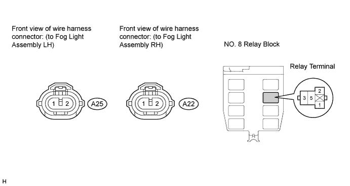
| 7.CHECK HARNESS AND CONNECTOR (FRONT FOG LIGHT RELAY - FOG LIGHT ASSEMBLY) |
for TMC Made
Disconnect the A25 fog light assembly LH connector and the A22 fog light assembly RH connector.
Measure the resistance according to the value(s) in the table below.
- Standard Resistance:
Tester Connection
| Condition
| Specified Condition
|
Front fog light relay terminal 3 - A25-2
| Always
| Below 1 Ω
|
Front fog light relay terminal 3 - Body ground
| Always
| 10 kΩ or higher
|
Front fog light relay terminal 3 - A22-2
| Always
| Below 1 Ω
|
Front fog light relay terminal 3 - Body ground
| Always
| 10 kΩ or higher
|
except TMC Made
Disconnect the A25 fog light assembly LH connector and the A22 fog light assembly RH connector.
Measure the resistance according to the value(s) in the table below.
- Standard Resistance:
Tester Connection
| Condition
| Specified Condition
|
Front fog light relay terminal 3 - A25-2
| Always
| Below 1 Ω
|
Front fog light relay terminal 3 - Body ground
| Always
| 10 kΩ or higher
|
Front fog light relay terminal 3 - A22-2
| Always
| Below 1 Ω
|
Front fog light relay terminal 3 - Body ground
| Always
| 10 kΩ or higher
|
| | REPAIR OR REPLACE HARNESS OR CONNECTOR |
|
|
| 8.CHECK HARNESS AND CONNECTOR (FOG LIGHT ASSEMBLY - BODY GROUND) |
Measure the resistance according to the value(s) in the table below.
- Standard Resistance:
Tester Connection
| Condition
| Specified Condition
|
A25-1 - Body ground
| Always
| Below 1 Ω
|
A22-1 - Body ground
| Always
| Below 1 Ω
|
| | REPAIR OR REPLACE HARNESS OR CONNECTOR |
|
|