INSTALL INSTRUMENT PANEL REINFORCEMENT ASSEMBLY (for Manual Air Conditioning System)
INSTALL INSTRUMENT PANEL REINFORCEMENT ASSEMBLY (for Automatic Air Conditioning System)
INSTALL NO. 1 INSTRUMENT PANEL BRACE SUB-ASSEMBLY (for Manual Air Conditioning System)
INSTALL NO. 1 INSTRUMENT PANEL BRACE SUB-ASSEMBLY (for Automatic Air Conditioning System)
Air Conditioning Unit -- Installation |
| 1. INSTALL BLOWER ASSEMBLY (w/o PTC Heater) |
Install the blower assembly with the 3 screws.
 |
for Automatic Air Conditioning System:
Connect the connector.
| 2. INSTALL BLOWER ASSEMBLY (w/ PTC Heater) |
Install the blower assembly with the 3 screws.
 |
Engage the quick heater connector and install the screw.
for Automatic Air Conditioning System:
Connect the connector.
Engage each clamp.
 |
| 3. INSTALL NO. 2 AIR DUCT SUB-ASSEMBLY |
Engage the 2 claws and install the No. 2 air duct sub-assembly.
 |
| 4. TEMPORARILY TIGHTEN AIR CONDITIONING UNIT |
Temporarily tighten the air conditioning unit with the bolt and the nut.
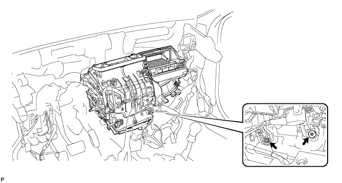
- NOTICE:
- Be sure to support the air conditioning unit assembly when removing it because failure to do so may cause the bracket of the air conditioning unit assembly to break.
- When installing the air conditioning unit, eliminate static electricity by touching the vehicle body to prevent the components from being damaged.
| 5. INSTALL INSTRUMENT PANEL REINFORCEMENT ASSEMBLY (for Manual Air Conditioning System) |
Install the instrument panel reinforcement assembly with the 7 bolts.
- Torque:
- <A>:
- 24 N*m{245 kgf*cm, 18 ft.*lbf}

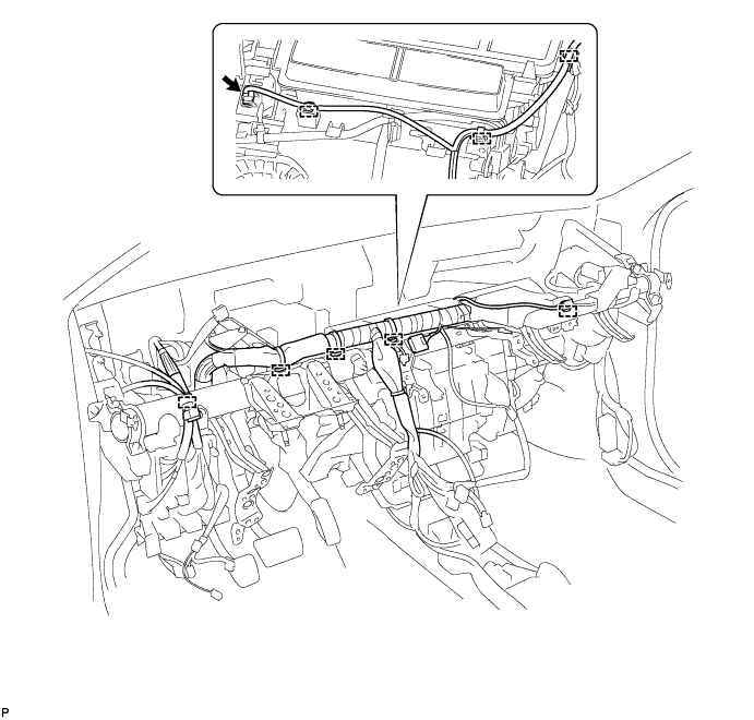
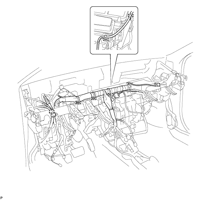
Connect each connector.
Engage each clamp.
Engage the wire harness and junction block with the 12 bolts.
- Torque:
- <A>:
- 8.4 N*m{86 kgf*cm, 74 in.*lbf}
Engage the cooler drain hose.

Engage each clamp and the wire harness.
| 6. INSTALL INSTRUMENT PANEL REINFORCEMENT ASSEMBLY (for Automatic Air Conditioning System) |
Install the instrument panel reinforcement assembly with the 7 bolts.
- Torque:
- <A>:
- 24 N*m{245 kgf*cm, 18 ft.*lbf}
Connect each connector.
Engage each clamp.
Engage the wire harness and junction block with the 12 bolts.
- Torque:
- <A>:
- 8.4 N*m{86 kgf*cm, 74 in.*lbf}
Engage the cooler drain hose.

Engage each clamp and the wire harness.
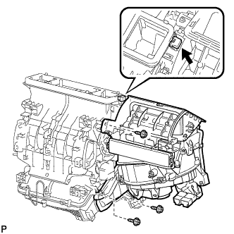
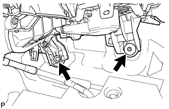
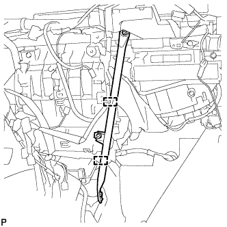
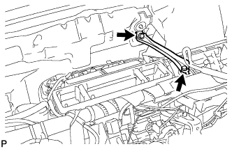
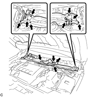
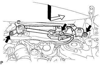
| 7. INSTALL AIR CONDITIONING UNIT |
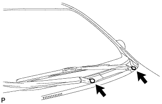
Install the 3 bolts.
- Torque:
- 9.8 N*m{100 kgf*cm, 87 in.*lbf}
- HINT:
- Tighten the bolts in the order shown in the illustration.
 |
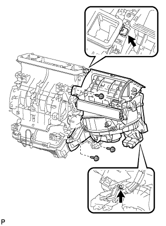
Install the bolt.
- Torque:
- 9.8 N*m{100 kgf*cm, 87 in.*lbf}
 |
Install the air conditioning unit with the nut.
- Torque:
- 9.8 N*m{100 kgf*cm, 87 in.*lbf}
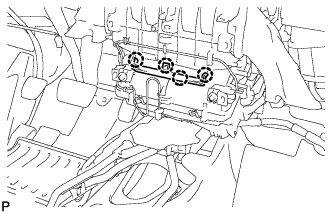
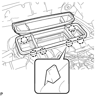
| 8. INSTALL HEATER COVER (w/ Cover) |
Engage the 4 claws and install the heater cover.
 |
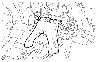
| 9. INSTALL REAR NO. 1 AIR DUCT (w/ Rear Air Duct) |
Engage the 4 claws and install the rear No. 1 air duct.
 |
| 10. INSTALL NO. 2 INSTRUMENT PANEL BRACE SUB-ASSEMBLY |
Install the No. 2 instrument panel brace sub-assembly with the bolt, screw and the nut.
- Torque:
- Screw:
- 9.8 N*m{100 kgf*cm, 87 in.*lbf}
 |
for TMC Made:
Engage the clamp.

except TMC Made:
Engage each clamp.
| 11. INSTALL NO. 1 INSTRUMENT PANEL BRACE SUB-ASSEMBLY (for Manual Air Conditioning System) |
Install the No. 1 instrument panel brace sub-assembly with the bolt, screw and the nut.
- Torque:
- Screw:
- 9.8 N*m{100 kgf*cm, 87 in.*lbf}
 |
for TMC Made:
Engage each clamp.
Connect the connector.
except TMC Made:
Engage each clamp.
Connect the connector.

| 12. INSTALL NO. 1 INSTRUMENT PANEL BRACE SUB-ASSEMBLY (for Automatic Air Conditioning System) |
Install the No. 1 instrument panel brace sub-assembly with the bolt, screw and the nut.
- Torque:
- Screw:
- 9.8 N*m{100 kgf*cm, 87 in.*lbf}
|
for TMC Made:
Engage each clamp.
except TMC Made:
Engage each clamp.
| 13. INSTALL REAR NO. 3 AIR DUCT (w/ Rear Air Duct) |
Engage the 2 claws to install the rear No. 3 air duct.
 |
Engage the clip and install the floor carpet.
 |
| 14. INSTALL REAR NO. 2 AIR DUCT (w/ Rear Air Duct) |
Engage the 2 claws to install the rear No. 2 air duct.
 |
Engage the clip and install the floor carpet.
 |
| 15. INSTALL CENTER INSTRUMENT PANEL TO COWL BRACE |
Install the center instrument panel to cowl brace with the 2 bolts.
 |
| 16. INSTALL LOWER DEFROSTER NOZZLE ASSEMBLY |
Engage the 6 claws and install the lower defroster nozzle assembly.
 |
| 17. INSTALL NO. 1 AIR DUCT SUB-ASSEMBLY |
Install the No. 1 air duct sub-assembly with the 2 nuts.
- Torque:
- 9.8 N*m{100 kgf*cm, 87 in.*lbf}
 |
| 18. INSTALL SMART KEY ECU ASSEMBLY (w/ Smart Key System) |
| 19. INSTALL LOWER INSTRUMENT PANEL SUB-ASSEMBLY |
| 20. INSTALL STEERING POST ASSEMBLY |
| 21. INSTALL POWER STEERING ECU ASSEMBLY (for 2ZR-FE) |
| 22. INSTALL POWER STEERING ECU ASSEMBLY (for 2AZ-FE) |
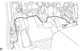
| 23. INSTALL HEATER OUTLET WATER HOSE |
Install the water hose and attach the clip.
 |
| 24. INSTALL HEATER INLET WATER HOSE |
- HINT:
- Use the same procedure described for the heater outlet water hose.
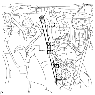
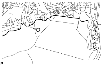
| 25. INSTALL AIR CONDITIONING TUBE ASSEMBLY |
Remove the attached vinyl tape from the tube.
Sufficiently apply compressor oil to a new O-ring and the fitting surface of the air conditioning tube assembly.
- Compressor oil:
- ND-OIL 8 or equivalent
Install the O-ring on the air conditioning tube assembly.
Install the air conditioning tube assembly.
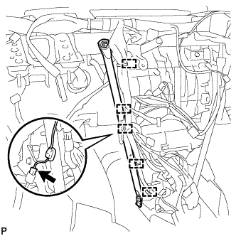
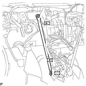
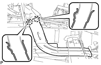
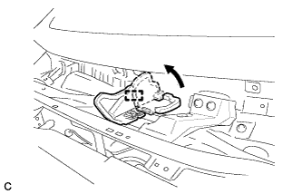
| 26. INSTALL SUCTION PIPE SUB-ASSEMBLY |
Remove the attached vinyl tape from the hose.
Sufficiently apply compressor oil to a new O-ring and the fitting surface of the suction hose sub-assembly.
- Compressor oil:
- ND-OIL 8 or equivalent
Install the O-ring on the suction hose sub-assembly.
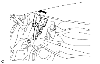
Move the hook connector in the direction indicated by the arrow in the illustration.
 |
Insert the pipe joint into the fitting hole securely and tighten the bolt.
- Torque:
- 9.8 N*m{100 kgf*cm, 87 in.*lbf}
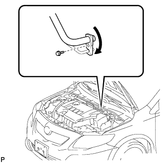
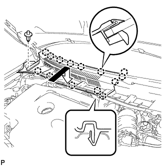
| 27. INSTALL OUTER COWL TOP PANEL (for TMC Made) |
Install the outer cowl top panel with the 12 bolts.
- Torque:
- 8.8 N*m{90 kgf*cm, 78 in.*lbf}
 |
Engage the clamp.
Bend the water guard plate RH as shown in the illustration and engage the clamp.
 |
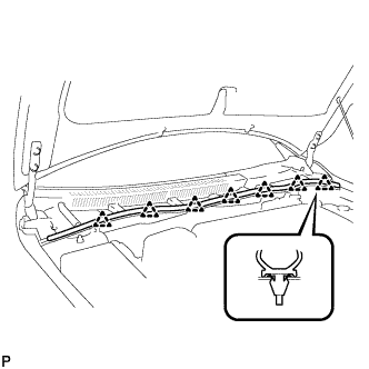
| 28. INSTALL OUTER COWL TOP PANEL (except TMC Made) |
Install the outer cowl top panel with the 12 bolts.
- Torque:
- 8.8 N*m{90 kgf*cm, 78 in.*lbf}
 |
Engage the clamp.
Bend the water guard plate RH as shown in the illustration, and engage the clamp.
|
Bend the No. 1 heater air duct splash shield seal as shown in the illustration, and engage the clamp.
 |
| 29. INSTALL WINDSHIELD WIPER MOTOR AND LINK ASSEMBLY |
Install the windshield wiper motor and link assembly with the 2 bolts.
- Torque:
- 5.5 N*m{56 kgf*cm, 49 in.*lbf}
 |
Connect the connector.
| 30. INSTALL COWL TOP VENTILATOR LOUVER LH |
Engage the clip and 8 claws to install the cowl top ventilator louver LH.
 |
| 31. INSTALL CENTER NO. 1 COWL TOP VENTILATOR LOUVER |
Engage the clip and 14 claws to install the center No. 1 cowl top ventilator louver.
 |
| 32. INSTALL HOOD TO COWL TOP SEAL |
Engage the 7 clips to install the hood to cowl top seal.
 |
| 33. INSTALL FRONT WIPER ARM AND BLADE ASSEMBLY RH |
Operate the wiper and stop the windshield wiper motor at the automatic stop position.
Clean the wiper arm serrations.
 |
When reinstalling:
Clean the wiper pivot serrations with a wire brush.
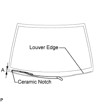
Install the front wiper arm and blade assembly RH with the nut to the position shown in the illustration.
- Torque:
- 26 N*m{265 kgf*cm, 19 ft.*lbf}
- HINT:
- Hold the arm hinge by hand while fastening the nut.
Area Measurement A 27.5 to 42.5 mm (1.08 to 1.67 in.)
 |
| 34. INSTALL FRONT WIPER ARM AND BLADE ASSEMBLY LH |
Operate the front wipers and stop the windshield wiper motor at the automatic stop position.
Clean the wiper arm serrations.
|
When reinstalling:
Clean the wiper pivot serrations with a wire brush.
Install the front wiper arm and blade assembly LH with the nut to the position shown in the illustration.
- Torque:
- 26 N*m{265 kgf*cm, 19 ft.*lbf}
- HINT:
- Hold the arm hinge by hand while fastening the nut.
Area Measurement A 31.5 to 46.5 mm (1.24 to 1.83 in.)
 |
Operate the front wipers while spraying washer fluid on the windshield glass. Make sure that the front wipers function properly and the wipers do not come into contact with the vehicle body.
| 35. INSTALL FRONT WIPER ARM HEAD CAP |
Install the 2 front wiper arm head caps.
 |
| 36. CHARGE WITH REFRIGERANT |
Perform vacuum purging using a vacuum pump.
Charge with refrigerant HFC-134a (R134a).
- Standard:
- 410 to 470 g (14.5 to 16.6 oz.)
- SST
- 09985-20010(09985-02130,09985-02150,09985-02090,09985-02110,09985-02010,09985-02050,09985-02060,09985-02070,09985-02140,09985-02080)
- NOTICE:
- Do not turn the A/C on before charging with refrigerant. Doing so will cause the cooler compressor to work without refrigerant, resulting in overheating of the cooler compressor.
- HINT:
- Ensure that sufficient refrigerant is available to recharge the system when using a refrigerant recovery unit. Refrigerant recovery units are not always able to recover 100% of the refrigerant from an A/C system.
| 37. ADD ENGINE COOLANT (for 2ZR-FE) |
Tighten the lower radiator drain cock plug.
Loosen the upper radiator drain cock plug.
Slowly fill the radiator with TOYOTA Super Long Life Coolant (SLLC).
- Standard Capacity:
Item Capacity Engine coolant 5.5 liters (5.8 US qts, 4.8 lmp. qts)
- HINT:
- TOYOTA vehicles are filled with TOYOTA SLLC at the factory. In order to avoid damage to the engine cooling system and other technical problems, only use TOYOTA SLLC or similar high quality ethylene glycol based non-silicate, non-amine, non-nitrite, non-borate coolant with long-life hybrid organic acid technology (coolant with long-life hybrid organic acid technology is a combination of low phosphates and organic acids).
- NOTICE:
- Never use water as a substitute for engine coolant.
Squeeze the inlet and outlet radiator hoses several times by hand, and then check the level of the coolant.
If the coolant level is low, add coolant.
Tighten the upper radiator drain cock plug.
Slowly pour coolant into the radiator reservoir tank until it reaches the FULL line.
Install the radiator cap sub-assembly and reservoir tank cap.
Start the engine and warm it up.
Bleed air from the cooling system.
- NOTICE:
- Before starting the engine, turn the A/C switch off.
- Adjust the air conditioning temperature setting to MAX (HOT).
- Adjust the air conditioning blower setting to LO.
Warm up the engine until the thermostat opens. While the thermostat is open, allow the coolant to circulate for several minutes.
- HINT:
- Thermostat opening timing can be determined by squeezing the inlet radiator hose, and sensing vibrations when the engine coolant starts to flow inside the hose.
- CAUTION:
- When squeezing the radiator hoses:
- Wear protective gloves.
- Be careful as the radiator hoses are hot.
- Keep your hands away from the radiator fan.
Stop the engine, and wait until the engine coolant cools down.
Add engine coolant to the FULL line on the radiator reservoir.
| 38. ADD ENGINE COOLANT (for 2AZ-FE) |
Tighten the lower radiator drain cock plug.
Tighten the cylinder block drain cock plug.
- Torque:
- 13 N*m{130 kgf*cm, 9 ft.*lbf}
Loosen the upper radiator drain cock plug.
Slowly fill the radiator with TOYOTA Super Long Life Coolant (SLLC).
- Standard Capacity:
Item Capacity Engine coolant 5.7 liters (6.0 US qts, 5.0 lmp. qts)
- HINT:
- TOYOTA vehicles are filled with TOYOTA SLLC at the factory. In order to avoid damage to the engine cooling system and other technical problems, only use TOYOTA SLLC or similar high quality ethylene glycol based non-silicate, non-amine, non-nitrite, non-borate coolant with long-life hybrid organic acid technology (coolant with long-life hybrid organic acid technology consists of a combination of low phosphates and organic acids).
- Contact your TOYOTA dealer for further details.
- NOTICE:
- Never use water as a substitute for engine coolant.
Squeeze the inlet and outlet radiator hoses several times by hand, and then check the level of the coolant.
If the coolant level is low, add coolant.
Tighten the upper radiator drain cock plug.
Slowly pour coolant into the radiator reservoir tank until it reaches the FULL line.
Install the radiator cap sub-assembly and reservoir tank cap.
Start the engine and warm it up.
Bleed air from the cooling system.
- NOTICE:
- Before starting the engine, turn the A/C switch off.
- Adjust the air conditioning temperature setting to MAX (HOT).
- Adjust the air conditioning blower setting to LO.
Warm up the engine until the thermostat opens. While the thermostat is open, allow the coolant to circulate for several minutes.
- HINT:
- Thermostat opening timing can be determined by squeezing the inlet radiator hose, and sensing vibrations when the engine coolant starts to flow inside the hose.
- CAUTION:
- When squeezing the radiator hoses:
- Wear protective gloves.
- Be careful as the radiator hoses are hot.
- Keep your hands away from the radiator fan.
Stop the engine, and wait until the engine coolant cools down.
Add engine coolant to the FULL line on the radiator reservoir.
| 39. INSPECT FOR COOLANT LEAK (for 2ZR-FE) |
- CAUTION:
- To avoid the danger of being burned, do not remove the radiator cap sub-assembly while the engine and radiator assembly are still hot. Thermal expansion will cause hot engine coolant and steam to blow out from the radiator assembly.
Fill the radiator assembly with engine coolant, then attach a radiator cap tester.
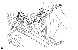 |
Pump it to 118 kPa (1.2 kgf/cm2, 17.0 psi), then check that the pressure does not drop.
If the pressure drops, check the hoses, radiator assembly and water pump assembly for leakage. If there are no signs or traces of external engine coolant leakage, check the heater core, cylinder block and head.
| 40. INSPECT FOR COOLANT LEAK (for 2AZ-FE) |
|
- CAUTION:
- To avoid the danger of being burned, do not remove the radiator cap sub-assembly while the engine and radiator assembly are still hot. Thermal expansion will cause hot engine coolant and steam to blow out from the radiator assembly.
Fill the radiator assembly with engine coolant, then attach a radiator cap tester.
Pump the tester to 118 kPa (1.2 kgf/cm2, 17.1 psi), then check that the pressure does not drop.
If the pressure drops, check the hoses, radiator assembly and water pump assembly for leakage. If there are no signs or traces of external engine coolant leakage, check the heater core, cylinder block and head.
| 41. WARM UP ENGINE |
Keep the A/C switch on for at least 2 minutes to warm up the compressor.
- NOTICE:
- Be sure to warm up the compressor when turning the A/C on after removing and installing the cooler refrigerant lines (including the compressor), to prevent damage to the compressor.
| 42. INSPECT FOR REFRIGERANT LEAK |
After recharging with refrigerant, inspect for refrigerant leaks using a halogen leak detector.
Carry out the test under the following conditions:
- Turn the ignition switch off.
- Secure good ventilation (the halogen leak detector may react to volatile gases which are not refrigerant, such as evaporated gasoline and exhaust gas).
- Repeat the test 2 or 3 times.
- Make sure that there is some refrigerant remaining in the refrigeration system.
When the compressor is off: approx. 392 to 588 kPa (3.9 to 5.9 kgf/cm2, 57 to 85 psi).
- Turn the ignition switch off.
Using a halogen leak detector, inspect for refrigerant leaks from the refrigerant lines.
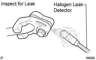 |
Bring the halogen leak detector close to the drain hose with the detector's power off, and then turn the detector on.
- HINT:
- After the blower motor has stopped, let the cooling unit stand for more than 15 minutes.
- Bring the halogen leak detector sensor under the drain hose.
- When bringing the halogen leak detector close to the drain hose, make sure that the halogen leak detector does not react to volatile gases.
If it is not possible to avoid interference from volatile gases, the vehicle should be lifted up to allow testing.
 |
If a refrigerant leak is not detected from the drain hose, remove the blower motor control from the cooling unit. Insert the halogen leak detector sensor into the unit and perform the test.
Disconnect the pressure switch connector and leave it for approximately 20 minutes. Bring the halogen leak detector close to the pressure switch and perform the test.