Manual Transaxle Unit Reassembly
INSTALL OUTPUT SHAFT COVER
INSTALL OUTPUT SHAFT FRONT BEARING
INSTALL FRONT TRANSAXLE CASE OIL SEAL
INSTALL INPUT SHAFT FRONT BEARING
INSTALL SHIFT AND SELECT LEVER SHAFT SLIDE BALL BEARING
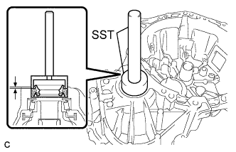
INSTALL SHIFT AND SELECT LEVER SHAFT OIL SEAL
INSTALL FRONT DIFFERENTIAL CASE FRONT TAPERED ROLLER BEARING
INSTALL FRONT DIFFERENTIAL CASE REAR TAPERED ROLLER BEARING
ADJUST DIFFERENTIAL SIDE BEARING PRELOAD
INSTALL TRANSMISSION CASE OIL SEAL
INSTALL TRANSAXLE CASE OIL SEAL
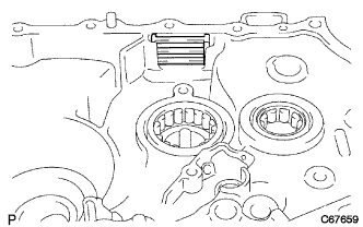
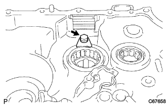
INSTALL TRANSMISSION MAGNET
INSTALL BEARING LOCK PLATE
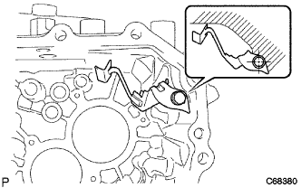
INSTALL NO. 1 OIL RECEIVER PIPE
INSTALL NO. 2 OIL RECEIVER PIPE
INSTALL REVERSE RESTRICT PIN ASSEMBLY
INSTALL MANUAL TRANSAXLE CASE RECEIVER
INSTALL DIFFERENTIAL CASE ASSEMBLY
INSTALL INPUT SHAFT ASSEMBLY
INSTALL REVERSE IDLER GEAR SUB-ASSEMBLY
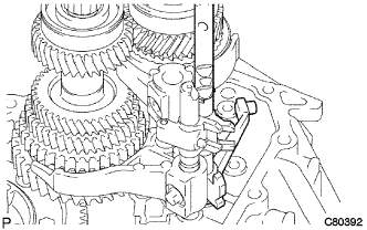
INSTALL NO. 1 GEAR SHIFT FORK SHAFT
INSTALL NO. 3 GEAR SHIFT FORK SHAFT
INSTALL NO. 2 GEAR SHIFT FORK SHAFT
INSTALL REVERSE SHIFT ARM BRACKET ASSEMBLY
INSTALL MANUAL TRANSMISSION CASE
INSTALL REVERSE IDLER GEAR SHAFT BOLT
INSTALL NO. 2 LOCK BALL ASSEMBLY
INSTALL SHIFT DETENT BALL
INSTALL INPUT SHAFT REAR BEARING HOLE SNAP RING
INSTALL OUTPUT SHAFT REAR BEARING HOLE SNAP RING
INSTALL SHIFT FORK SHAFT SNAP RING
INSTALL REAR BEARING RETAINER
INSTALL 5TH DRIVEN GEAR
INSTALL 5TH GEAR NEEDLE ROLLER BEARING
INSTALL 5TH GEAR
INSTALL NO. 3 SYNCHRONIZER RING
INSTALL NO. 3 TRANSMISSION CLUTCH HUB
INSPECT 5TH GEAR THRUST CLEARANCE
INSPECT 5TH GEAR RADIAL CLEARANCE
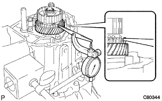
INSTALL NO. 3 GEAR SHIFT FORK
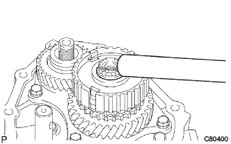
INSTALL MANUAL TRANSMISSION OUTPUT SHAFT REAR SET NUT
INSTALL MANUAL TRANSMISSION CASE COVER SUB-ASSEMBLY
INSTALL SHIFT AND SELECT LEVER SHAFT ASSEMBLY
INSTALL CONTROL SHAFT COVER OIL SEAL
INSTALL CONTROL SHAFT COVER
INSTALL SHIFT GUIDE PIN
INSTALL NO. 1 LOCK BALL ASSEMBLY
INSTALL SHIFT LEVER DAMPER
INSTALL FLOOR SHIFT CONTROL SHIFT LEVER
INSTALL SELECTING BELLCRANK ASSEMBLY
INSTALL BACK-UP LIGHT SWITCH ASSEMBLY
INSTALL SPEEDOMETER DRIVEN HOLE COVER SUB-ASSEMBLY
INSTALL MANUAL TRANSMISSION FILLER PLUG
INSTALL DRAIN PLUG SUB-ASSEMBLY
Manual Transaxle Unit -- Reassembly |
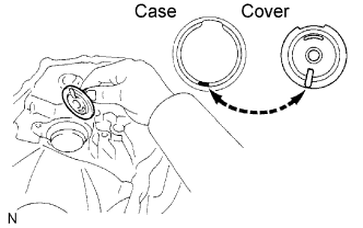
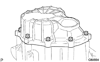
| 1. INSTALL OUTPUT SHAFT COVER |
Coat the output shaft cover with MP grease and install it onto the transaxle case.
- NOTICE:
- Insert the output shaft cover key into the case groove.
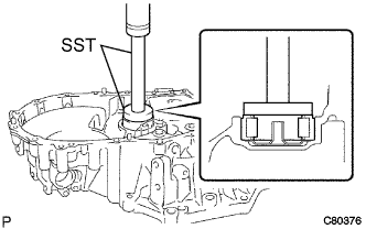
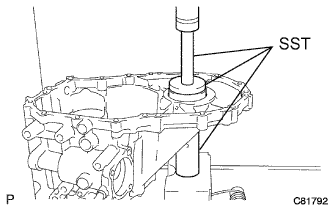
| 2. INSTALL OUTPUT SHAFT FRONT BEARING |
Coat a new output shaft front bearing with gear oil.
Using SST and a press, install it onto the transaxle case.
- SST
- 09950-60010(09951-00550)
09950-70010(09951-07150)
- NOTICE:
- Install the new bearing in the correct direction as shown in the illustration.
- When replacing the output shaft front bearing, replace the output shaft front bearing inner race at the same time.
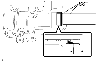
| 3. INSTALL FRONT TRANSAXLE CASE OIL SEAL |
Using SST and a hammer, install a new front transaxle case oil seal onto the transaxle case.
- SST
- 09950-60010(09951-00370)
09950-70010(09951-07150)
- Driven in depth:
- 15.6 to 16.0 mm (0.6141 to 0.6299 in.)
Coat the lip of the front transaxle case oil seal with MP grease.
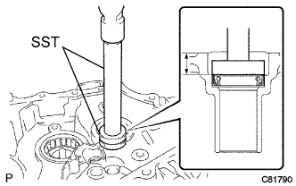
| 4. INSTALL INPUT SHAFT FRONT BEARING |
Coat a new input shaft front bearing with gear oil, and using SST and a press, install it onto the transaxle case.
- SST
- 09950-60010(09951-00420)
09950-70010(09951-07150)
- Driven in depth:
- 0 to 0.3 mm (0 to 0.0118 in.)
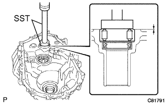
| 5. INSTALL SHIFT AND SELECT LEVER SHAFT SLIDE BALL BEARING |
Using SST and a hammer, install a new shift and select lever shaft slide ball bearing onto the manual transmission case.
- SST
- 09950-60010(09951-00220)
09950-70010(09951-07100)
- Driven in depth:
- 0 to 0.5 mm (0 to 0.0197 in.)
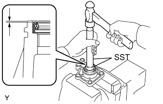
| 6. INSTALL SHIFT AND SELECT LEVER SHAFT OIL SEAL |
Using SST, install a new shift and select lever shaft oil seal onto the manual transmission case.
- SST
- 09950-70010(09951-07150)
09950-60010(09951-00240)
- Driven in depth:
- 9.7 to 10.3 mm (0.382 to 0.406 in.)
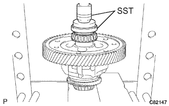
| 7. INSTALL FRONT DIFFERENTIAL CASE FRONT TAPERED ROLLER BEARING |
Using SST and a press, install a new front differential case front tapered roller bearing (inner race) onto the front differential case.
- SST
- 09350-32014(09351-32120)
09950-60010(09951-00530)
Using SST and a press, install the front differential case front tapered roller bearing (outer race) together with the plate washer onto the transaxle case.
- SST
- 09950-60020(09951-00680)
09950-70010(09951-07150)
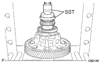
| 8. INSTALL FRONT DIFFERENTIAL CASE REAR TAPERED ROLLER BEARING |
Using SST and a press, install a new front differential case rear tapered roller bearing (inner race) to the differential case.
- SST
- 09350-32014(09351-32120)
09950-60010(09951-00530)
Using SST and a press, install the front differential case rear tapered roller bearing (outer race) with the plate washer onto the manual transmission case.
- SST
- 09309-36010
09950-60020(09951-00710)
09950-70010(09951-07150)
- HINT:
- Use a plate washer of the same thickness as the removed one.
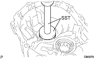
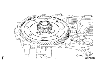
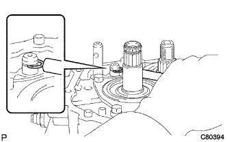
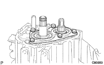
| 9. ADJUST DIFFERENTIAL SIDE BEARING PRELOAD |
Coat the differential case assembly with gear oil and install it onto the transaxle case.
Install the manual transmission case with the 16 bolts.
- Torque:
- 29 N*m{300 kgf*cm, 22 ft.*lbf}
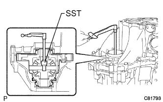
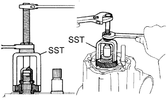
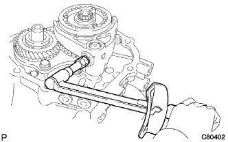
Using SST and a torque wrench, turn the differential case assembly clockwise and counterclockwise 2 or 3 times to allow the bearings to settle.
- SST
- 09564-32011
Using SST and a torque wrench, measure the preload.
- SST
- 09564-32011
- Preload (at starting):
- New bearing:
- 0.8 to 1.5 N*m (8 to 16 kgf*cm, 7 to 13 in.*lbf)
- Used bearing:
- 0.5 to 0.9 N*m (5 to 10 kgf*cm, 5 to 8 in.*lbf)
If the preload is out of the specification, select a different plate washer.
- Plate Washer Thickness:
Mark
| Thickness
mm (in.)
| Mark
| Thickness
mm (in.)
|
AA
| 2.10 (0.0827)
| LL
| 2.60 (0.102)
|
BB
| 2.15 (0.0846)
| MM
| 2.65 (0.104)
|
CC
| 2.20 (0.0866)
| NN
| 2.70 (0.106)
|
DD
| 2.25 (0.0886)
| PP
| 2.75 (0.108)
|
EE
| 2.30 (0.0906)
| QQ
| 2.80 (0.110)
|
FF
| 2.35 (0.0925)
| RR
| 2.85 (0.112)
|
GG
| 2.40 (0.0945)
| SS
| 2.90 (0.114)
|
HH
| 2.45 (0.0965)
| TT
| 2.95 (0.1161)
|
JJ
| 2.50 (0.0984)
| UU
| 3.00 (0.118)
|
KK
| 2.55 (0.1004)
| -
| -
|
- HINT:
- The preload changes by approximately 0.3 to 0.4 N*m (3 to 4 kgf*cm, 3 to 4 in.*lbf) per each 0.05 mm (0.0020 in.) change in the plate washer thickness.
Remove the 16 bolts and the manual transmission case.
Remove the differential case assembly from the transaxle case.
| 10. INSTALL TRANSMISSION CASE OIL SEAL |
Using SST and a hammer, install a new transmission case oil seal onto the manual transmission case.
- SST
- 09316-60011(09316-00011)
- Driven in depth:
- 9.6 to 10.2 mm (0.378 to 0.402 in.)
Coat the lip of the front transmission case oil seal with MP grease.
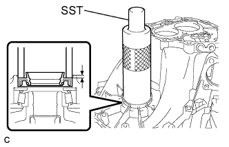
| 11. INSTALL TRANSAXLE CASE OIL SEAL |
Using SST and a hammer, install a new transaxle case oil seal onto the transaxle case.
- SST
- 09710-20011(09710-06071)
09950-70010(09951-07150)
- Driven in depth:
- 1.4 to 2.0 mm (0.0551 to 0.0787 in.)
Coat the lip of the transaxle case oil seal with MP grease.
| 12. INSTALL TRANSMISSION MAGNET |
Clean the transmission magnet and install it onto the transaxle case.
| 13. INSTALL BEARING LOCK PLATE |
Install the bearing lock plate onto the transaxle case with the bolt.
- Torque:
- 11 N*m{115 kgf*cm, 8 ft.*lbf}
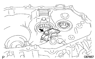
| 14. INSTALL NO. 1 OIL RECEIVER PIPE |
Install the No. 1 oil receiver pipe onto the manual transmission case with the bolt.
- Torque:
- 17 N*m{175 kgf*cm, 13 ft.*lbf}
- NOTICE:
- Do not deform the No. 1 oil receiver pipe.
- Install the No. 1 oil receiver pipe while holding it against the manual transmission case as shown in the illustration.
| 15. INSTALL NO. 2 OIL RECEIVER PIPE |
Install the No. 2 oil receiver pipe onto the manual transmission case with the bolt.
- Torque:
- 17 N*m{175 kgf*cm, 13 ft.*lbf}
- NOTICE:
- Do not deform the No. 2 oil receiver pipe.
- Install the No. 2 oil receiver pipe while holding it against the manual transmission case as shown in the illustration.
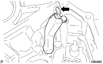
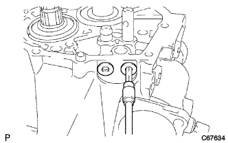
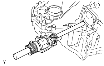
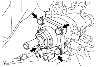
| 16. INSTALL REVERSE RESTRICT PIN ASSEMBLY |
Install the reverse restrict pin assembly onto the manual transmission case.
- NOTICE:
- Set the reverse restrict pin assembly in the correct direction.
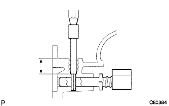
Using a pin punch (φ5 mm) and a hammer, install the slotted spring pin onto the reverse restrict pin assembly.
- Drive in depth:
- 15.5 to 16.5 mm (0.6102 to 0.6496 in.)
Apply sealant to the reverse restrict pin plug.
- Sealant:
- Toyota Genuine Adhesive 1344, Three Bond 1344 or equivalent
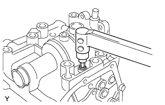
Using a hexagon wrench and a torque wrench, install the reverse restrict pin plug onto the manual transmission case.
- Torque:
- 13 N*m{130 kgf*cm, 9 ft.*lbf}
| 17. INSTALL MANUAL TRANSAXLE CASE RECEIVER |
Install the manual transaxle case receiver onto the transaxle case with the bolt.
- Torque:
- 11 N*m{115 kgf*cm, 8 ft.*lbf}
| 18. INSTALL DIFFERENTIAL CASE ASSEMBLY |
Coat the differential case tapered roller bearing with gear oil and install the differential case assembly onto the transaxle case.
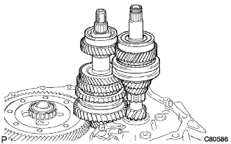
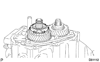
| 19. INSTALL INPUT SHAFT ASSEMBLY |
Coat the sliding and rotating surfaces of the input and output shafts with gear oil and install them onto the transaxle case.
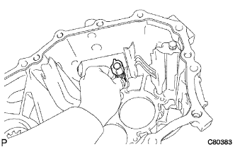
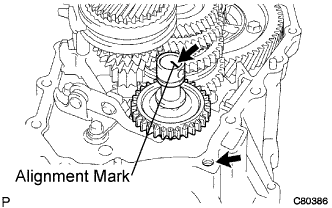
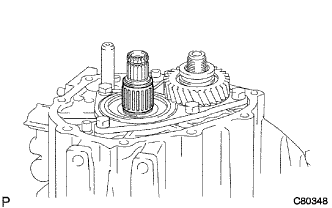
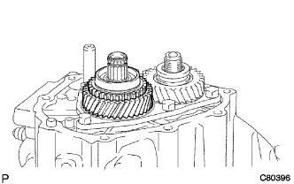
| 20. INSTALL REVERSE IDLER GEAR SUB-ASSEMBLY |
Coat the reverse idler gear sub-assembly, thrust washer and reverse idler gear shaft with gear oil, and install them as shown in the illustration.
- HINT:
- Align the mark on the reverse idler gear shaft with the bolt hole as shown in the illustration.
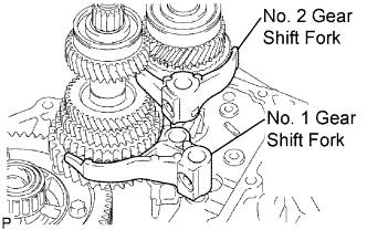
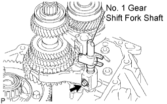
| 21. INSTALL NO. 1 GEAR SHIFT FORK SHAFT |
Coat the No. 1 gear shift fork and No. 2 gear shift fork with gear oil and install them.
Coat the No. 1 gear shift fork shaft with gear oil and install it.
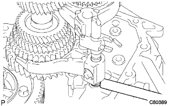
Apply sealant to the shift fork set bolt.
- Sealant:
- Toyota Genuine Adhesive 1344, Three Bond 1344 or equivalent
Install the shift fork set bolt.
- Torque:
- 16 N*m{160 kgf*cm, 12 ft.*lbf}
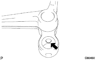
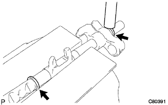
Using a brass bar and a hammer, install a new shaft snap ring onto the No. 1 gear shift fork shaft.
| 22. INSTALL NO. 3 GEAR SHIFT FORK SHAFT |
Coat the 2 shift fork balls with MP grease and install them onto the reverse shift fork.
Install the reverse shift fork onto the No. 3 gear shift fork shaft.
Using a brass bar and a hammer, install 2 new shift fork shaft snap rings onto the No. 3 shift fork shaft.
Coat the No. 3 gear shift fork shaft with gear oil and install it.
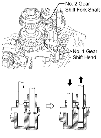
| 23. INSTALL NO. 2 GEAR SHIFT FORK SHAFT |
Coat the No. 1 gear shift head and No. 2 gear shift fork shaft with gear oil and install them.
- NOTICE:
- To avoid interference from the 2 shift fork balls, lift up the No. 3 gear shift fork shaft to the position shown in the illustration.
Coat the 2 shift lock bolts with sealant and install them onto the No. 2 gear shift fork and No. 1 shift head.
- Sealant:
- Toyota Genuine Adhesive 1344, Three Bond 1344 or equivalent
- Torque:
- 16 N*m{160 kgf*cm, 12 ft.*lbf}
| 24. INSTALL REVERSE SHIFT ARM BRACKET ASSEMBLY |
Install the reverse shift arm bracket assembly onto the front transaxle case with the 2 bolts.
- Torque:
- 17 N*m{175 kgf*cm, 13 ft.*lbf}
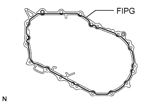
| 25. INSTALL MANUAL TRANSMISSION CASE |
Apply FIPG to the manual transmission case as shown in the illustration.
- FIPG:
- Toyota Genuine Seal Packing 1281, Three Bond 1281 or equivalent
- NOTICE:
- Assemble the parts within 10 minutes of application. Otherwise, the packing (FIPG) material must be removed and reapplied.
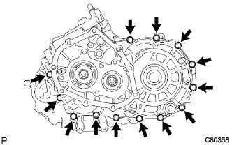
Install the 13 bolts onto the manual transmission side.
- Torque:
- 29 N*m{300 kgf*cm, 22 ft.*lbf}
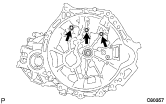
Coat the 3 bolts with sealant and install them onto the manual transaxle side.
- Sealant:
- Toyota Genuine Adhesive 1344, Three Bond 1344 or equivalent
- Torque:
- 29 N*m{300 kgf*cm, 22 ft.*lbf}
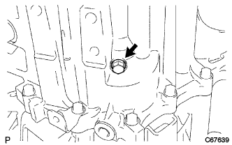
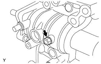
| 26. INSTALL REVERSE IDLER GEAR SHAFT BOLT |
Coat the reverse idler gear shaft bolt with sealant and install it with a new gasket.
- Sealant:
- Toyota Genuine Adhesive 1344, Three Bond 1344 or equivalent
- Torque:
- 29 N*m{300 kgf*cm, 22 ft.*lbf}
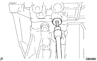
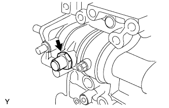
| 27. INSTALL NO. 2 LOCK BALL ASSEMBLY |
Coat the No. 2 lock ball assembly with sealant and install it using a hexagon wrench.
- Sealant:
- Toyota Genuine Adhesive 1344, Three Bond 1344 or equivalent
- Torque:
- 29 N*m{300 kgf*cm, 22 ft.*lbf}
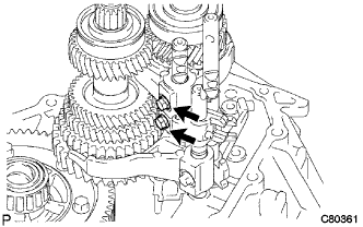
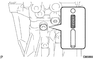
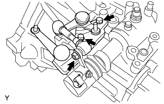
| 28. INSTALL SHIFT DETENT BALL |
Install the 2 shift detent balls, 2 shift detent ball springs, and 2 shift spring seats onto the manual transmission case.
Coat the threads of the 2 shift detent ball plugs with sealant and install them using a hexagon wrench.
- Sealant:
- Toyota Genuine Adhesive 1344, Three Bond 1344 or equivalent
- Torque:
- 22 N*m{224 kgf*cm, 16 ft.*lbf}
Install the shift detent ball, shift detent ball compression spring, and spring seat onto the transaxle case.
Coat the threads of the shift detent ball plug with sealant and install it using a hexagon wrench.
- Sealant:
- Toyota Genuine Adhesive 1344, Three Bond 1344 or equivalent
- Torque:
- 22 N*m{224 kgf*cm, 16 ft.*lbf}
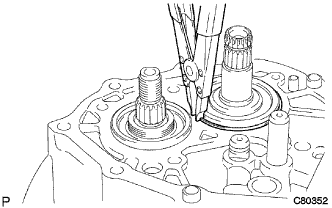
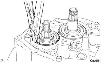
| 29. INSTALL INPUT SHAFT REAR BEARING HOLE SNAP RING |
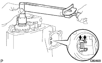
Using a snap ring expander, install a new input shaft rear bearing hole snap ring onto the input shaft.
| 30. INSTALL OUTPUT SHAFT REAR BEARING HOLE SNAP RING |
Using a snap ring expander, install a new output shaft rear bearing hole snap ring onto the output shaft.
| 31. INSTALL SHIFT FORK SHAFT SNAP RING |
Using a brass bar and a hammer, install a new shift fork shaft snap ring onto the No. 2 shift fork shaft.
| 32. INSTALL REAR BEARING RETAINER |
Coat the 5 bolts with sealant and install the rear bearing retainer onto the manual transmission case with the 5 bolts.
- Sealant:
- Toyota Genuine Adhesive 1344, Three Bond 1344 or equivalent
- Torque:
- 27 N*m{280 kgf*cm, 20 ft.*lbf}
| 33. INSTALL 5TH DRIVEN GEAR |
Using SST, install the 5th driven gear onto the output shaft.
- SST
- 09309-12020
| 34. INSTALL 5TH GEAR NEEDLE ROLLER BEARING |
Coat the 5th gear needle roller bearing and 5th gear bearing spacer with gear oil, and install them onto the input shaft.
Coat the 5th gear with gear oil and install it onto the input shaft.
| 36. INSTALL NO. 3 SYNCHRONIZER RING |
Coat the No. 3 synchronizer ring with gear oil and install it onto the 5th gear.
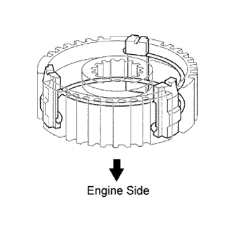
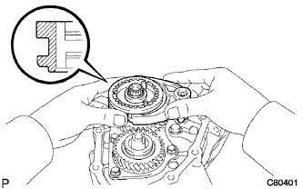
| 37. INSTALL NO. 3 TRANSMISSION CLUTCH HUB |
Install the 3 synchromesh shifting keys and 2 synchromesh shifting key springs onto the No. 3 transmission clutch hub as shown in the illustration.
- NOTICE:
- Do not set the 2 shifting key spring openings in the same position.
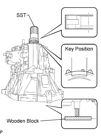
Using SST and a hammer, install the No. 3 transmission clutch hub onto the input shaft.
- SST
- 09636-20010
- NOTICE:
- Do not install the No. 3 transmission clutch hub in the wrong direction.
- Install the No. 3 transmission clutch hub with the No. 3 synchronizer ring key groove and the No. 3 synchromesh shifting key aligned.
- Check that the 5th gear can rotate smoothly.
- Place a suitable sized wooden block to support the input shaft.
Select a snap ring that will allow minimum axial play.
- Clearance:
- 0.1 mm (0.00394 in.) or less
- Snap Ring Thickness:
Mark
| Thickness
mm (in.)
| Mark
| Thickness
mm (in.)
|
A
| 2.25 (0.0886)
| E
| 2.49 (0.0980)
|
B
| 2.31 (0.0909)
| F
| 2.55 (0.1004)
|
C
| 2.37 (0.0933)
| G
| 2.61 (0.1028)
|
D
| 2.43 (0.0957)
| -
| -
|
Using a brass bar and a hammer, install a new snap ring onto the input shaft.
| 38. INSPECT 5TH GEAR THRUST CLEARANCE |
Using a dial indicator, measure the 5th gear thrust clearance.
- Standard clearance:
- 0.10 to 0.55 mm (0.00394 to 0.0217 in.)
- Maximum clearance:
- 0.55 mm (0.0217 in.)
If the clearance exceeds the maximum, replace the No. 3 transmission clutch hub, 5th gear or input shaft rear radial ball bearing.
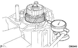
| 39. INSPECT 5TH GEAR RADIAL CLEARANCE |
Using a dial indicator, measure the 5th gear radial clearance.
- Standard clearance:
- NSK made bearing:
- 0.015 to 0.056 mm (0.000591 to 0.00220 in.)
- JTEKT made bearing:
- 0.015 to 0.058 mm (0.000591 to 0.00228 in.)
- Maximum clearance:
- NSK made bearing:
- 0.056 mm (0.00220 in.)
- JTEKT made bearing:
- 0.058 mm (0.00228 in.)
If the clearance exceeds the maximum, replace the 5th gear, 5th gear needle roller bearing or input shaft.
| 40. INSTALL NO. 3 GEAR SHIFT FORK |
Coat the No. 3 transmission clutch hub sleeve with gear oil and install it together with the No. 3 gear shift fork onto the No. 3 transmission clutch hub.
- HINT:
- Set the No. 3 transmission clutch hub in the correct direction.
Coat the gear shift fork lock bolt with sealant and install it onto the No. 3 gear shift fork.
- Sealant:
- Toyota Genuine Adhesive 1344, Three Bond 1344 or equivalent
- Torque:
- 16 N*m{160 kgf*cm, 12 ft.*lbf}
| 41. INSTALL MANUAL TRANSMISSION OUTPUT SHAFT REAR SET NUT |
Engage 2 gears simultaneously to lock the transmission.
Install a new manual transmission output shaft rear set nut.
- Torque:
- 118 N*m{1200 kgf*cm, 87 ft.*lbf}
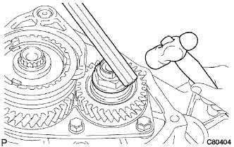
Using a chisel and a hammer, stake the manual transmission output shaft rear set nut.
Disengage the 2 gears.
| 42. INSTALL MANUAL TRANSMISSION CASE COVER SUB-ASSEMBLY |
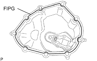
Apply FIPG to the manual transmission case cover sub-assembly as shown in the illustration.
- FIPG:
- Toyota Genuine Seal Packing 1281, Three Bond 1281 or equivalent
- NOTICE:
- Assemble the parts within 10 minutes of application. Otherwise, the packing (FIPG) material must be removed and reapplied.
Install the manual transmission case cover sub-assembly onto the manual transmission case with the 9 bolts.
- Torque:
- 21 N*m{214 kgf*cm, 15 ft.*lbf}
| 43. INSTALL SHIFT AND SELECT LEVER SHAFT ASSEMBLY |
Coat the shift and select lever shaft assembly with gear oil and install it onto the transmission case.
| 44. INSTALL CONTROL SHAFT COVER OIL SEAL |
Using SST and a hammer, install a new control shaft cover oil seal onto the control shaft cover.
- SST
- 09950-60010(09951-00280)
09950-70010(09951-07150)
- Driven in depth:
- 0.2 to 1.2 mm (0.00787 to 0.0472 in.)
Coat the control shaft cover oil seal with MP grease.
| 45. INSTALL CONTROL SHAFT COVER |
Coat the threads of the 4 bolts with sealant. Install a new gasket and the control shaft cover onto the manual transmission case with the 4 bolts.
- Sealant:
- Toyota Genuine Adhesive 1344, Three Bond 1344 or equivalent
- Torque:
- 20 N*m{200 kgf*cm, 14 ft.*lbf}
- NOTICE:
- Set the claws of the shift interlock plate into the shift head part of the gear shift fork shaft securely.
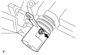
| 46. INSTALL SHIFT GUIDE PIN |
Coat the threads of the shift guide pin with sealant.
- Sealant:
- Toyota Genuine Adhesive 1344, Three Bond 1344 or equivalent
Install the washer and shift guide pin.
- Torque:
- 11 N*m{112 kgf*cm, 8 ft.*lbf}
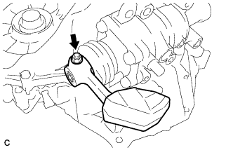
| 47. INSTALL NO. 1 LOCK BALL ASSEMBLY |
Coat the threads of the No. 1 lock ball assembly with sealant and install it onto the manual transmission case.
- Sealant:
- Toyota Genuine Adhesive 1344, Three Bond 1344 or equivalent
- Torque:
- 29 N*m{300 kgf*cm, 22 ft.*lbf}
| 48. INSTALL SHIFT LEVER DAMPER |
Install the dust boot onto the control shaft cover.
Install the shift lever damper with the lock pin onto the shift and select lever shaft assembly.
Install the washer with the nut.
- Torque:
- 12 N*m{120 kgf*cm, 9 ft.*lbf}
| 49. INSTALL FLOOR SHIFT CONTROL SHIFT LEVER |
Install the dust boot onto the shift and select lever shaft oil seal.
Install the floor shift control shift lever with the lock pin onto the shift and select lever shaft assembly.
Install the washer with the nut.
- Torque:
- 12 N*m{120 kgf*cm, 9 ft.*lbf}
| 50. INSTALL SELECTING BELLCRANK ASSEMBLY |
Install the selecting bellcrank assembly together with the control bellcrank dust cover onto the manual transmission case with the 2 bolts and nut.
- Torque:
- 25 N*m{250 kgf*cm, 18 ft.*lbf} for bolt
- 12 N*m{120 kgf*cm, 9 ft.*lbf} for nut
- NOTICE:
- Apply MP grease to the inside surface of the control shift lever bush.
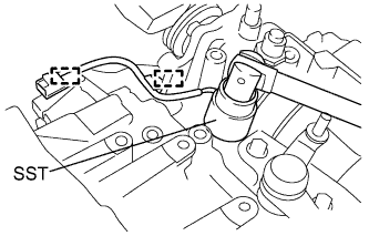
| 51. INSTALL BACK-UP LIGHT SWITCH ASSEMBLY |
Using SST, install the back-up light switch assembly onto the manual transmission case with a new gasket.
- SST
- 09817-16011
- Torque:
- 40 N*m{410 kgf*cm, 30 ft.*lbf}
Install the back-up light switch wire harness into the 2 clamps.
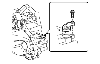
| 52. INSTALL SPEEDOMETER DRIVEN HOLE COVER SUB-ASSEMBLY |
Install a new O-ring onto the speedometer driven hole cover sub-assembly.
Install the speedometer driven hole cover sub-assembly onto the manual transaxle case with the bolt.
- Torque:
- 11 N*m{115 kgf*cm, 8 ft.*lbf}
| 53. INSTALL MANUAL TRANSMISSION FILLER PLUG |
Install the manual transmission filler plug onto the manual transmission case with a new gasket.
- Torque:
- 39 N*m{400 kgf*cm, 29 ft.*lbf}
| 54. INSTALL DRAIN PLUG SUB-ASSEMBLY |
Install the drain plug onto the manual transmission case with a new gasket.
- Torque:
- 39 N*m{400 kgf*cm, 29 ft.*lbf}