Output Shaft -- Reassembly |
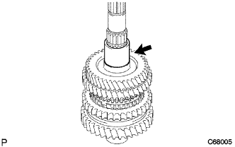
| 1. INSTALL REVERSE GEAR |
Coat the reverse gear and No. 1 transmission clutch hub with gear oil.
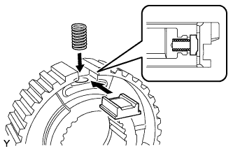 |
Install the 3 synchromesh shifting key springs and 3 synchromesh keys to the No. 1 transmission clutch hub.
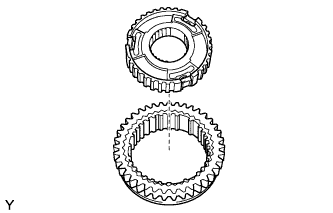
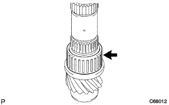
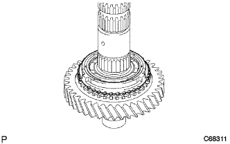
Install the reverse gear onto the No. 1 transmission clutch hub assembly.
- NOTICE:
- Position the reverse gear and No. 1 transmission clutch hub correctly as shown in the illustration.
 |
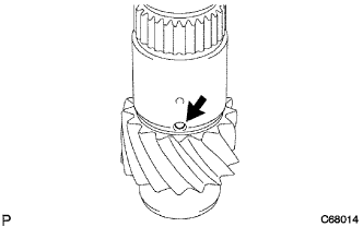
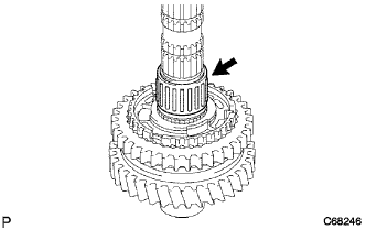
| 2. INSTALL 1ST GEAR THRUST WASHER PIN OR BALL |
Coat the 1st gear thrust washer pin or ball with MP grease and install it onto the output shaft.
 |
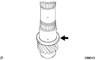
| 3. INSTALL 1ST GEAR THRUST WASHER |
Coat the 1st gear thrust washer with gear oil and install it onto the output shaft.
 |
| 4. INSTALL 1ST GEAR NEEDLE ROLLER BEARING |
Coat the 1st gear needle roller bearing with gear oil and install it onto the output shaft.
 |
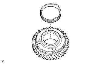
| 5. INSTALL NO. 1 SYNCHRONIZER RING SET (FOR 1ST GEAR) |
Coat the 1st gear cone and No. 1 synchronizer ring set (inner ring, middle ring, and outer ring) with gear oil.
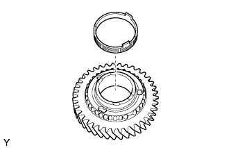 |
Install the inner ring onto the 1st gear.
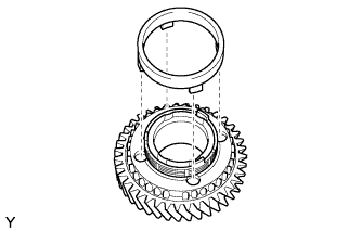
Install the middle ring onto the 1st gear.
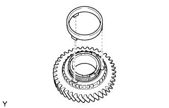 |
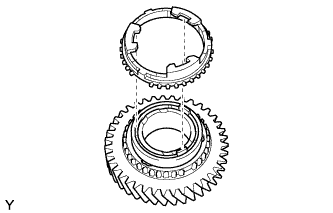
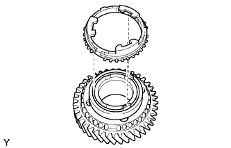
Install the outer ring onto the 1st gear.
 |
| 6. INSTALL 1ST GEAR |
Coat the 1st gear with gear oil and install it onto the output shaft.
 |
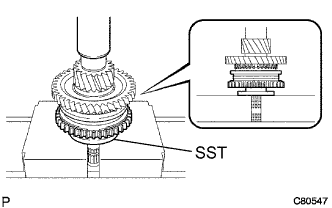
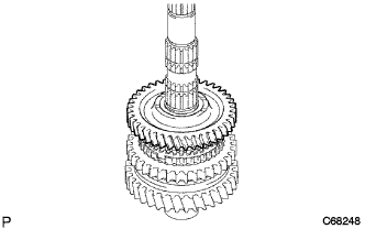
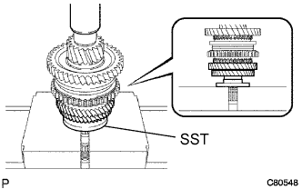
| 7. INSTALL NO. 1 TRANSMISSION CLUTCH HUB |
Using SST and a press, install the No. 1 transmission clutch hub onto the output shaft.
- SST
- 09316-60011(09316-00031)
- HINT:
- Make sure that the 1st gear can be turned.
- While checking that the 1st gear thrust washer pin or ball is inserted into the groove of the 1st gear thrust washer, press and fit the No. 1 clutch hub.
 |
Select a snap ring that will allow minimum axial play.
- Standard clearance:
- 0.1 mm (0.00394 in.) or less
- Snap Ring Thickness:
Mark Thickness
mm (in.)Mark Thickness
mm (in.)A 2.50 (0.0984) D 2.68 (0.1055) B 2.56 (0.1008) E 2.74 (0.1079) C 2.62 (0.1031) F 2.80 (0.1102)
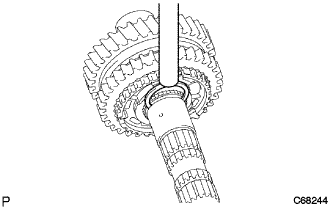 |
Using a brass bar and a hammer, install the snap ring onto the output shaft.
- NOTICE:
- Do not damage the journal surface of the output shaft.
| 8. INSTALL 2ND GEAR NEEDLE ROLLER BEARING |
Coat the 2nd gear needle roller bearing and 2nd gear bearing spacer with gear oil, and install them onto the output shaft.
 |
| 9. INSTALL NO. 2 SYNCHRONIZER RING SET (FOR 2ND GEAR) |
Coat the 2nd gear cone and No. 2 synchronizer ring set (inner ring, middle ring, and outer ring) with gear oil.
 |
Install the inner ring onto the 2nd gear.
Install the middle ring onto the 2nd gear.
 |
Install the outer ring onto the 2nd gear.
 |
| 10. INSTALL 2ND GEAR |
Coat the 2nd gear with gear oil and install it onto the output shaft.
 |
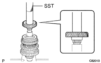
| 11. INSTALL 3RD DRIVEN GEAR |
Using SST and a press, install the 3rd driven gear onto the output shaft.
- SST
- 09316-60011(09316-00031)
 |
| 12. INSTALL OUTPUT GEAR SPACER |
Install the output gear spacer onto the output shaft.
 |
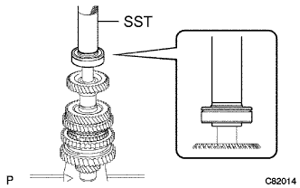
| 13. INSTALL 4TH DRIVEN GEAR |
Using SST and a press, install the 4th driven gear onto the output shaft.
- SST
- 09612-22011
 |
| 14. INSTALL OUTPUT SHAFT REAR BEARING |
Using SST and a press, install the output shaft rear bearing onto the output shaft.
- SST
- 09612-22011
 |
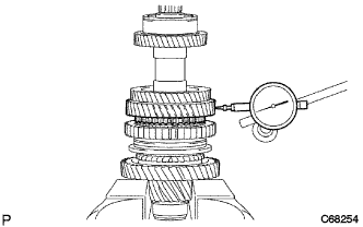
| 15. INSPECT 2ND GEAR RADIAL CLEARANCE |
Using a dial indicator, measure the 2nd gear radial clearance.
- Standard clearance:
- NSK made bearing:
- 0.015 to 0.056 mm (0.000591 to 0.00220 in.)
- JTEKT made bearing:
- 0.015 to 0.058 mm (0.000591 to 0.00228 in.)
- Maximum clearance:
- NSK made bearing:
- 0.056 mm (0.00220 in.)
- JTEKT made bearing:
- 0.058 mm (0.00228 in.)
 |
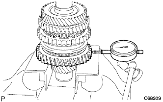
| 16. INSPECT 1ST GEAR RADIAL CLEARANCE |
Using a dial indicator, measure the 1st gear radial clearance.
- Standard clearance:
- NSK made bearing:
- 0.015 to 0.056 mm (0.000591 to 0.00220 in.)
- JTEKT made bearing:
- 0.015 to 0.058 mm (0.000591 to 0.00228 in.)
- Maximum clearance:
- NSK made bearing:
- 0.056 mm (0.00220 in.)
- JTEKT made bearing:
- 0.058 mm (0.00228 in.)
 |
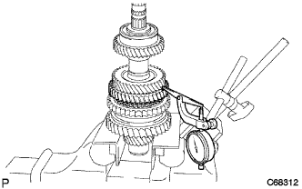
| 17. INSPECT 2ND GEAR THRUST CLEARANCE |
Using a dial indicator, measure the 2nd gear thrust clearance.
- Standard clearance:
- 0.10 to 0.55 mm (0.00394 to 0.0217 in.)
- Maximum clearance:
- 0.55 mm (0.0217 in.)
 |
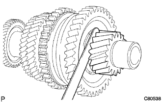
| 18. INSPECT 1ST GEAR THRUST CLEARANCE |
Using a feeler gauge, measure the 1st gear thrust clearance.
- Standard clearance:
- 0.10 to 0.40 mm (0.00394 to 0.0157 in.)
- Maximum clearance:
- 0.40 mm (0.0157 in.)
 |