REMOVE SUSPENSION TOWER DAMPER ASSEMBLY (w/ Front Strut Bar)
REMOVE FUEL DELIVERY PIPE SUB-ASSEMBLY WITH FUEL TUBE SUB-ASSEMBLY
Knock Sensor -- Removal |
| 1. DISCHARGE FUEL SYSTEM PRESSURE |
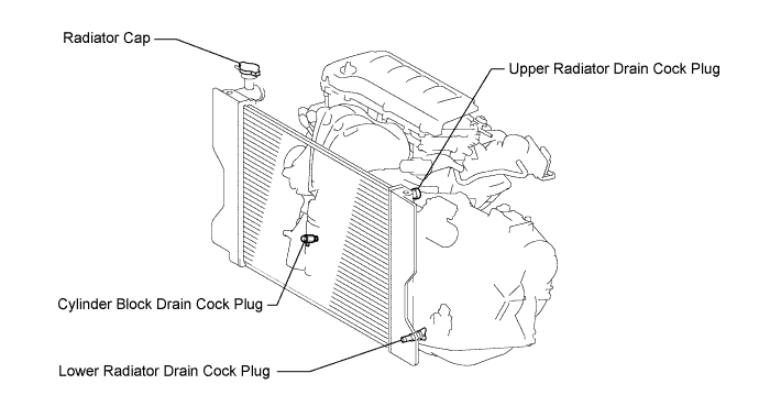
| 2. DRAIN COOLANT |
Loosen the lower radiator drain cock plug.
- CAUTION:
- Do not loosen the lower radiator drain cock plug while the engine and radiator are still hot.
- Pressurized, hot engine coolant and steam may be released and cause serious burns.
- HINT:
- Collect the coolant in a container and dispose of it according to the regulations in your area.
Remove the radiator cap.
Loosen the cylinder block drain cock plug.
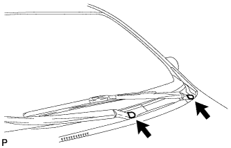
| 3. REMOVE FRONT WIPER ARM HEAD CAP |
Remove the 2 front wiper arm head caps.
 |
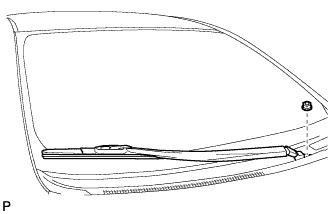
| 4. REMOVE FRONT WIPER ARM AND BLADE ASSEMBLY LH |
Remove the nut and the front wiper arm and blade assembly LH.
 |
| 5. REMOVE FRONT WIPER ARM AND BLADE ASSEMBLY RH |
Remove the nut and the front wiper arm and blade assembly RH.
 |
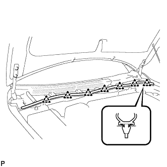
| 6. REMOVE HOOD TO COWL TOP SEAL |
Disengage the 7 clips and remove the hood to cowl top seal.
 |
| 7. REMOVE CENTER NO. 1 COWL TOP VENTILATOR LOUVER |
Disengage the clip and 14 claws, and remove the center No. 1 cowl top ventilator louver.
 |
| 8. REMOVE COWL TOP VENTILATOR LOUVER LH |
Disengage the clip and 8 claws, and remove the cowl top ventilator louver LH.
 |
| 9. REMOVE WINDSHIELD WIPER MOTOR AND LINK ASSEMBLY |
Disconnect the connector.
 |
Remove the 2 bolts and the windshield wiper motor and link assembly.
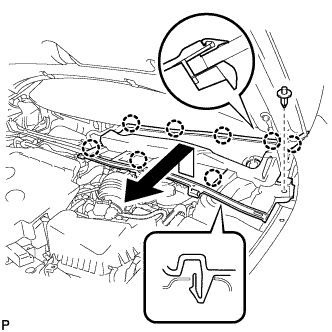
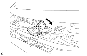
| 10. REMOVE OUTER COWL TOP PANEL |
Disengage the clamp and bend the water guard plate RH as shown in the illustration.
 |
Disengage the clamp.
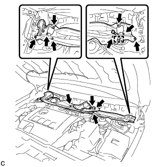 |
Remove the 12 bolts and outer cowl top panel.
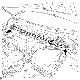
| 11. REMOVE SUSPENSION TOWER DAMPER ASSEMBLY (w/ Front Strut Bar) |
Remove the 2 nuts and suspension tower damper assembly.
 |
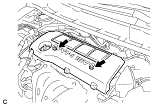
| 12. REMOVE NO. 1 ENGINE COVER SUB-ASSEMBLY |
Remove the 2 nuts and No. 1 engine cover sub-assembly.
 |
| 13. REMOVE AIR CLEANER CAP SUB-ASSEMBLY WITH HOSE |
Disconnect the mass air flow meter connector.
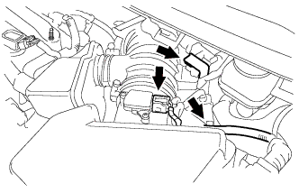 |
Separate the 2 wire harness clamps.
Disconnect the No. 1 vacuum switching valve connector and the 2 vacuum hoses.
 |
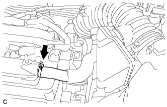
Disconnect the ventilation hose.
 |
Loosen the No. 1 air cleaner hose clamp, release the 3 air cleaner assembly clamps and remove the air cleaner cap sub-assembly with No. 1 hose.
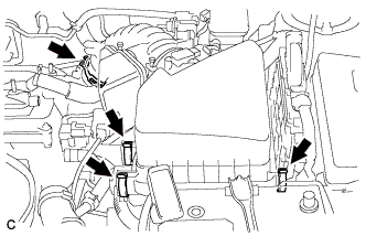 |
| 14. REMOVE THROTTLE BODY ASSEMBLY |
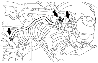
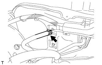
Disconnect the 2 water by-pass hoses.
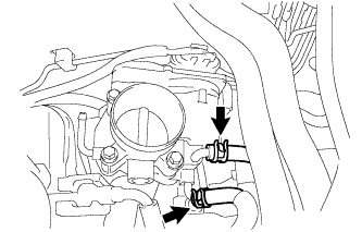 |
Disconnect the throttle body assembly connector.
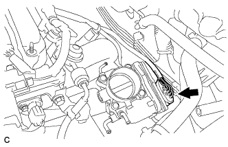 |
Remove the 4 bolts and throttle body assembly.
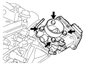 |
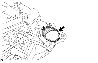
Remove the gasket from the intake manifold.
 |
| 15. DISCONNECT FUEL TUBE SUB-ASSEMBLY |
- NOTICE:
- Do not forcibly bend, kink or twist the fuel main tube.
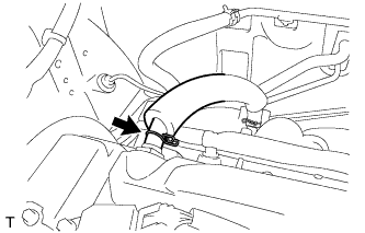
Remove the fuel tube from the fuel hose clamp.
 |
Remove the fuel pipe clamp.
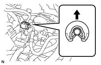
Wipe off any dirt on the fuel tube connector.
Hold the fuel tube connector, and then install SST.
- SST
- 09268-21011
 |
Turn SST to align the retainer inside the fuel tube connector with the chamfered part of SST.
Insert SST into the fuel tube and hold it. Then push the fuel tube connector toward SST.
Mount the retainer of the fuel tube connector onto the chamfered part of SST.
Slide SST and fuel tube connector together towards the fuel tube until they make a "click" sound, and then disconnect the fuel tube.
 |
Drain the fuel remaining inside the fuel tube.
Cover the fuel tube and fuel pipe with a plastic bag to protect the disconnected part.
| 16. REMOVE FUEL DELIVERY PIPE SUB-ASSEMBLY WITH FUEL TUBE SUB-ASSEMBLY |
Remove the 2 wire harness clamps.
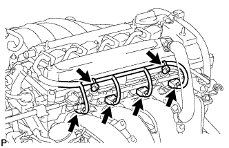 |
Disconnect the 4 fuel injector connectors.
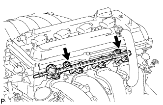
Remove the 2 bolts, then remove the fuel delivery pipe together with the 4 fuel injectors.
- NOTICE:
- Be careful not to drop the fuel injectors when removing the fuel delivery pipe.
 |
Remove the 2 delivery pipe spacers from the cylinder head.
 |
Remove the 4 insulators from the cylinder head.
| 17. REMOVE INTAKE MANIFOLD |
 |
Disconnect the ventilation hose.
Disconnect the union to check valve hose.
 |
Separate the wire harness clamp from the intake manifold.
Remove the 5 bolts, 2 nuts and intake manifold.
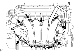 |
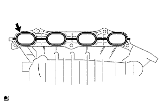
Remove the intake manifold gasket.
 |
| 18. REMOVE NO. 1 INTAKE MANIFOLD INSULATOR |
Remove the No. 1 intake manifold insulator.
| 19. REMOVE KNOCK SENSOR |
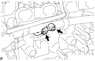 |
Disconnect the sensor connector.
Remove the nut and knock sensor.