Meter / Gauge System Fuel Receiver Gauge Malfunction
DESCRIPTION
WIRING DIAGRAM
INSPECTION PROCEDURE
PERFORM ACTIVE TEST USING TECHSTREAM (FUEL METER OPERATION)
READ VALUE USING TECHSTREAM (FUEL INPUT)
CHECK HARNESS AND CONNECTOR (COMBINATION METER - FUEL SENDER GAUGE ASSEMBLY)
INSPECT FUEL SENDER GAUGE ASSEMBLY
METER / GAUGE SYSTEM - Fuel Receiver Gauge Malfunction |
DESCRIPTION
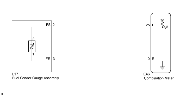
- The meter CPU uses the fuel sender gauge assembly to determine the level of the fuel in the fuel tank. The resistance of the fuel sender gauge will vary between approximately 15.0 Ω with the float at the full position, and 410.0 Ω with the float at the empty position. The meter outputs battery voltage through two 820 Ω resistors that are mounted in parallel inside the meter CPU. The meter CPU measures the voltage between the variable resistor in the fuel sender gauge and the two resistors mounted in parallel in the meter. Voltage measured at this point will vary as the float of the fuel sender gauge is moved. The highest voltage observed should be approximately half of battery voltage.
- HINT:
- The fuel level warning light will come on when the fuel level is below 7.5 liters (2.0 gallons).
WIRING DIAGRAM
INSPECTION PROCEDURE
| 1.PERFORM ACTIVE TEST USING TECHSTREAM (FUEL METER OPERATION) |
Connect the Techstream to the DLC3.
Turn the ignition switch to ON.
Turn the Techstream on.
Enter following menus: Body Electrical / Combination Meter / Active Test.
Check the operation by referring to the table below.
Combination MeterTester Display
| Test Part
| Control Range
| Diagnostic Note
|
Fuel Meter Operation
| Fuel receiver gauge
| EMPTY, 1/2, FULL
| Confirm that the vehicle is stopped, engine idling
|
- OK:
- Gauge indication is normal.
| 2.READ VALUE USING TECHSTREAM (FUEL INPUT) |
Connect the Techstream to the DLC3.
Turn the ignition switch to ON.
Turn the Techstream on.
Enter following menus: Body Electrical / Combination Meter / Data List.
Check the values by referring to the table below.
Combination MeterTester Display
| Measurement Item/Range
| Normal Condition
| Diagnostic Note
|
Fuel Input
| Fuel input signal Min.: 0, Max.: 127.5
| Fuel gauge indicates (E): 5.5 (L)
| -
|
Fuel gauge indicates (1/2): 27.5 (L)
|
Fuel gauge indicates (F): 49.5 (L)
|
- OK:
- Fuel value signal displayed on the Techstream is almost the same as fuel receiver gauge indication.
| 3.CHECK HARNESS AND CONNECTOR (COMBINATION METER - FUEL SENDER GAUGE ASSEMBLY) |
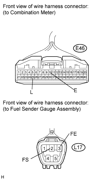
Disconnect the E46 and L17 connectors.
Measure the resistance according to the value(s) in the table below.
- Standard Resistance:
Tester Connection
| Condition
| Specified Condition
|
E46-10 (E) - L17-3 (FE)
| Always
| Below 1 Ω
|
L17-3 (FE) - Body ground
| Always
| 10 kΩ or higher
|
E46-25 (L) - L17-2 (FS)
| Always
| Below 1 Ω
|
E46-25 (L) - Body ground
| Always
| 10 kΩ or higher
|
| | REPAIR OR REPLACE HARNESS OR CONNECTOR |
|
|
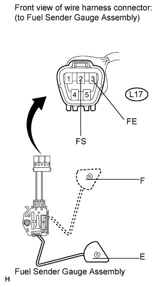
| 4.INSPECT FUEL SENDER GAUGE ASSEMBLY |
Remove the fuel sender gauge assembly.
Check that the float moves smoothly between E and F.
Measure the resistance according to the value(s) in the table below.
- Standard Resistance:
Tester Connection
| Condition
| Specified Condition
|
L17-2 (FS) - L17-3 (FE)
| Float level is F (upper)
| 13.5 to 16.5 Ω
|
L17-2 (FS) - L17-3 (FE)
| Float level is between F (upper) and E (lower)
| 13.5 to 414.5 Ω (Gradually changes)
|
L17-2 (FS) - L17-3 (FE)
| Float level is E (lower)
| 405.5 to 414.5 Ω
|
- Result:
Result
| Proceed to
|
OK
| A
|
NG (for 2AZ-FE)
| B
|
NG (for 2ZR-FE)
| C
|