DESCRIPTION
WIRING DIAGRAM
INSPECTION PROCEDURE
CHECK CONNECTORS
CHECK OCCUPANT CLASSIFICATION SYSTEM CIRCUIT (SHORT TO B+)
CHECK OCCUPANT CLASSIFICATION SYSTEM CIRCUIT (OPEN)
CHECK OCCUPANT CLASSIFICATION SYSTEM CIRCUIT (SHORT)
CHECK OCCUPANT CLASSIFICATION SYSTEM CIRCUIT (SHORT TO GROUND)
RECHECK FOR DTC
REPLACE OCCUPANT CLASSIFICATION ECU
RECHECK FOR DTC
PERFORM SENSITIVITY CHECK
REPLACE CENTER AIRBAG SENSOR ASSEMBLY
PERFORM SENSITIVITY CHECK
CHECK NO. 2 FLOOR WIRE (SHORT TO B+)
CHECK NO. 2 FLOOR WIRE (OPEN)
CHECK NO. 2 FLOOR WIRE (SHORT)
CHECK NO. 2 FLOOR WIRE (SHORT TO GROUND)
DTC B1790 Center Airbag Sensor Assembly Communication Circuit Malfunction |
DESCRIPTION
The center airbag sensor assembly communication circuit consists of the occupant classification ECU and the center airbag sensor assembly.DTC B1790 is recorded when a malfunction is detected in the center airbag sensor assembly communication circuit.DTC No.
| DTC Detecting Condition
| Trouble Area
|
B1790
| - The occupant classification ECU receives a short circuit signal, an open circuit signal and short circuit to ground signal or a short circuit to B+ signal in the center airbag sensor assembly communication circuit for 2 seconds.
- Center airbag sensor assembly malfunction
- Occupant classification ECU malfunction
| - No. 2 floor wire
- Front seat wire RH
- Occupant classification ECU
- Center airbag sensor assembly
|
- HINT:
- When DTC B1650/32 is detected as a result of troubleshooting for the airbag system, check the DTCs stored in the occupant classification ECU. When DTC B1790 is output, perform troubleshooting for the DTC.
WIRING DIAGRAM
INSPECTION PROCEDURE
- HINT:
- If troubleshooting (wire harness inspection) is difficult to perform, remove the front passenger seat installation bolts to access the underside of the seat cushion.
- In the above case, hold the seat so that it does not fall down. Holding the seat for a long period of time may damage the seat or deform the seat rails. Hold the seat only as necessary.
Turn the ignition switch off.
Disconnect the cable from the negative (-) battery terminal, and wait for at least 90 seconds.
Check that the connectors are properly connected to the occupant classification ECU and the center airbag sensor assembly.
- OK:
- The connectors are properly connected.
- HINT:
- If the connectors are not connected securely, reconnect the connectors and proceed to the next inspection.
Disconnect the connectors from the center airbag sensor assembly and the occupant classification ECU.
Check that the terminals of the connectors are not damaged.
- OK:
- The terminals are not deformed or damaged.
| 2.CHECK OCCUPANT CLASSIFICATION SYSTEM CIRCUIT (SHORT TO B+) |
Connect the cable to the negative (-) battery terminal.
Turn the ignition switch to ON.
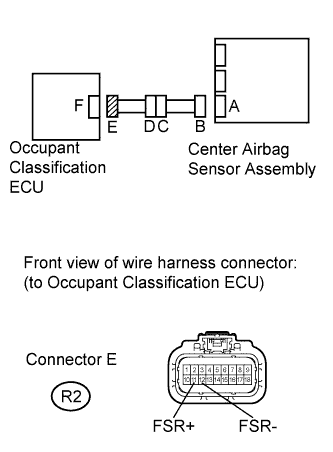
Measure the voltage according to the value(s) in the table below.
- Standard Voltage:
Tester Connection
| Switch Condition
| Specified Condition
|
R2-11 (FSR+) - Body ground
| Ignition switch ON
| Below 1 V
|
R2-12 (FSR-) - Body ground
| Ignition switch ON
| Below 1 V
|
| 3.CHECK OCCUPANT CLASSIFICATION SYSTEM CIRCUIT (OPEN) |
Turn the ignition switch off.
Disconnect the cable from the negative (-) battery terminal, and wait for at least 90 seconds.
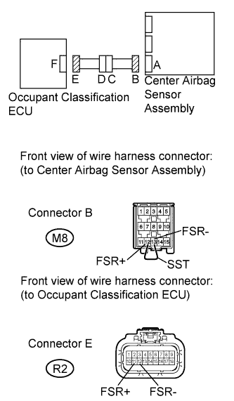
Using SST, connect terminals 12 (FSR+) and 13 (FSR-) of connector B.
- NOTICE:
- Do not forcibly insert SST into the terminals of the connector when connecting the wire.
- SST
- 09843-18040
Measure the resistance according to the value(s) in the table below.
- Standard Resistance:
Tester Connection
| Condition
| Specified Condition
|
R2-11 (FSR+) - R2-12 (FSR-)
| Always
| Below 1 Ω
|
| 4.CHECK OCCUPANT CLASSIFICATION SYSTEM CIRCUIT (SHORT) |
Disconnect SST from connector B.
Measure the resistance according to the value(s) in the table below.
- Standard Resistance:
Tester Connection
| Condition
| Specified Condition
|
R2-11 (FSR+) - R2-12 (FSR-)
| Always
| 1 MΩ or higher
|
| 5.CHECK OCCUPANT CLASSIFICATION SYSTEM CIRCUIT (SHORT TO GROUND) |
Measure the resistance according to the value(s) in the table below.
- Standard Resistance:
Tester Connection
| Condition
| Specified Condition
|
R2-11 (FSR+) - Body ground
| Always
| 1 MΩ or higher
|
R2-12 (FSR-) - Body ground
| Always
| 1 MΩ or higher
|
Connect the connectors to the occupant classification ECU and the center airbag sensor assembly.
Connect the Techstream to the DLC3.
Connect the cable to the negative (-) battery terminal.
Turn the ignition switch to ON.
Clear the DTCs stored in the occupant classification ECU (COROLLA_ZRE142 RM0000010VK07TX.html).
Clear the DTCs stored in the center airbag sensor assembly (COROLLA_ZRE142 RM000000XFE0H1X.html).
Turn the ignition switch off.
Turn the ignition switch to ON.
Using the Techstream, check for occupant classification ECU DTCs (COROLLA_ZRE142 RM0000010VK07TX.html).
- OK:
- DTC B1790 is not output.
- HINT:
- Codes other than DTC B1790 may be output at this time, but they are not related to this check.
| 7.REPLACE OCCUPANT CLASSIFICATION ECU |
Connect the Techstream to the DLC3.
Turn the ignition switch to ON.
Using the Techstream, save the ECU data from the ECU currently installed on the vehicle (COROLLA_ZRE142 RM000001QX402OX.html).
Turn the ignition switch off.
Disconnect the cable from the negative (-) battery terminal.
Replace the occupant classification ECU (COROLLA_ZRE142 RM0000011JG03CX.html).
Connect the cable to the negative (-) battery terminal.
Turn the ignition switch to ON.
Using the Techstream, load the previous ECU data stored into the new ECU (COROLLA_ZRE142 RM000001QX402OX.html).
Turn the ignition switch off.
Turn the ignition switch to ON.
Clear the DTCs stored in the memory (COROLLA_ZRE142 RM0000010VK07TX.html).
- HINT:
- If the DTCs are not cleared at this time, past DTCs will remain.
Turn the ignition switch to ON.
Clear the DTCs stored in the occupant classification ECU (COROLLA_ZRE142 RM0000010VK07TX.html).
Clear the DTCs stored in the center airbag sensor assembly (COROLLA_ZRE142 RM000000XFE0H1X.html).
Turn the ignition switch off.
Turn the ignition switch to ON.
Using the Techstream, check for occupant classification ECU DTCs (COROLLA_ZRE142 RM0000010VK07TX.html).
- OK:
- DTC B1790 is not output.
- HINT:
- Codes other than DTC B1790 may be output at this time, but they are not related to this check.
| 9.PERFORM SENSITIVITY CHECK |
Perform the sensitivity check (COROLLA_ZRE142 RM0000010VN07SX.html).
| 10.REPLACE CENTER AIRBAG SENSOR ASSEMBLY |
Turn the ignition switch off.
Disconnect the cable from the negative (-) battery terminal, and wait for at least 90 seconds.
Replace the center airbag sensor assembly (COROLLA_ZRE142 RM000000UWV074X.html).
| 11.PERFORM SENSITIVITY CHECK |
Perform the sensitivity check (COROLLA_ZRE142 RM0000010VN07SX.html).
| 12.CHECK NO. 2 FLOOR WIRE (SHORT TO B+) |
Turn the ignition switch off.
Disconnect the cable from the negative (-) battery terminal, and wait for at least 90 seconds.
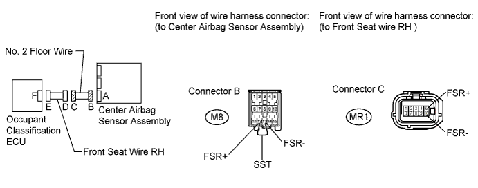
Disconnect the front seat wire RH connector from the No. 2 floor wire.
Connect the cable to the negative (-) battery terminal.
Turn the ignition switch to ON.
Measure the voltage according to the value(s) in the table below.
- Standard Voltage:
Tester Connection
| Switch Condition
| Specified Condition
|
MR1-5 (FSR+) - Body ground
| Ignition switch ON
| Below 1 V
|
MR1-10 (FSR-) - Body ground
| Ignition switch ON
| Below 1 V
|
| OK |
|
|
|
| REPLACE FRONT SEAT WIRE RH |
|
| 13.CHECK NO. 2 FLOOR WIRE (OPEN) |
Disconnect the front seat wire RH connector from the No. 2 floor wire.
- HINT:
- SST has already been inserted into connector B.
Measure the resistance according to the value(s) in the table below.
- Standard Resistance:
Tester Connection
| Condition
| Specified Condition
|
MR1-5 (FSR+) - MR1-10 (FSR-)
| Always
| Below 1 Ω
|
| OK |
|
|
|
| REPLACE FRONT SEAT WIRE RH |
|
| 14.CHECK NO. 2 FLOOR WIRE (SHORT) |
Disconnect the front seat wire RH connector from the No. 2 floor wire.
Measure the resistance according to the value(s) in the table below.
- Standard Resistance:
Tester Connection
| Condition
| Specified Condition
|
MR1-5 (FSR+) - MR1-10 (FSR-)
| Always
| 1 MΩ or higher
|
| OK |
|
|
|
| REPLACE FRONT SEAT WIRE RH |
|
| 15.CHECK NO. 2 FLOOR WIRE (SHORT TO GROUND) |
Disconnect the front seat wire RH connector from the No. 2 floor wire.
Measure the resistance according to the value(s) in the table below.
- Standard Resistance:
Tester Connection
| Condition
| Specified Condition
|
MR1-5 (FSR+) - Body ground
| Always
| 1 MΩ or higher
|
MR1-10 (FSR-) - Body ground
| Always
| 1 MΩ or higher
|
| OK |
|
|
|
| REPLACE FRONT SEAT WIRE RH |
|