Cylinder Head -- Inspection |
| 1. INSPECT CYLINDER HEAD FOR WARPAGE |
Using a precision straight edge and a feeler gauge, measure the surface contacting the cylinder block and the manifolds for warpage.
- Maximum Warpage:
Item Specified Condition Cylinder block side 0.08 mm (0.00315 in.) Intake manifold side 0.08 mm (0.00315 in.) Exhaust manifold side 0.08 mm (0.00315 in.)
 |
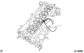
| 2. INSPECT CYLINDER HEAD FOR CRACKS |
Using a dye penetrant, check the intake ports, exhaust ports and cylinder surface for cracks.
If cracked, replace the cylinder head.
 |
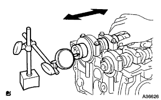
| 3. INSPECT CAMSHAFT THRUST CLEARANCE |
Install the camshafts (COROLLA_ZRE142 RM00000224800UX_01_0017.html).
Using a dial indicator, measure the thrust clearance while moving the camshaft back and forth.
- Standard Thrust Clearance:
Item Specified Condition Intake 0.040 to 0.095 mm (0.00157 to 0.00374 in.) Exhaust 0.090 to 0.145 mm (0.00354 to 0.00570 in.)
- Maximum Thrust Clearance:
Item Specified Condition Intake 0.110 mm (0.00433 in.) Exhaust 0.150 mm (0.00591 in.)
 |
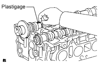
| 4. INSPECT CAMSHAFT OIL CLEARANCE |
Clean the bearing caps and camshaft journals.
Place the camshafts on the cylinder head.
Lay a strip of Plastigage across each of the camshaft journals.
 |
Install the bearing caps (COROLLA_ZRE142 RM00000224800UX_01_0017.html).
- NOTICE:
- Do not turn the camshaft.
Remove the bearing caps (COROLLA_ZRE142 RM00000224700UX_01_0028.html).
Measure the Plastigage at its widest point.
- Standard Oil Clearance:
Item Specified Condition Camshaft No. 1 journal bearing mark 1 0.007 to 0.038 mm (0.000276 to 0.00150 in.) Camshaft No. 1 journal bearing mark 2 0.008 to 0.038 mm (0.000315 to 0.00150 in.) Camshaft No. 1 journal bearing mark 3 0.008 to 0.038 mm (0.000315 to 0.00150 in.) Camshaft other journals 0.025 to 0.062 mm (0.000984 to 0.00244 in.) No. 2 camshaft No. 1 journal 0.040 to 0.072 mm (0.00157 to 0.00283 in.) No. 2 camshaft other journals 0.025 to 0.062 mm (0.000984 to 0.00244 in.)
- Maximum Oil Clearance:
Item Specified Condition Intake 0.070 mm (0.00276 in.) Exhaust 0.100 mm (0.00394 in.)
- NOTICE:
- Completely remove the Plastigage after the inspection.
- If the oil clearance is greater than the maximum, replace the camshaft. If necessary, replace the cylinder head.
- If the oil clearance on the camshaft No. 1 journal is greater than the maximum, choose a new bearing and install it.
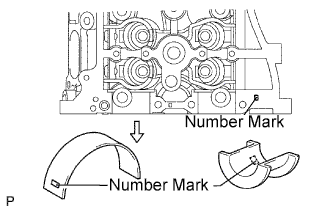
Check the number mark shown in the illustration.
- Cylinder Head Journal Bore Diameter:
Mark 1 Mark 2 Mark 3 40.000 to 40.009 mm (1.5748 to 1.5752 in.) 40.010 to 40.017 mm (1.5752 to 1.5755 in.) 40.018 to 40.025 mm (1.5755 to 1.5758 in.)
- Standard Bearing Center Wall Thickness:
Mark 1 Mark 2 Mark 3 2.000 to 2.004 mm (0.0787 to 0.0789 in.) 2.005 to 2.008 mm (0.0789 to 0.0791 in.) 2.009 to 2.012 mm (0.0791 to 0.0792 in.)
- Camshaft journal diameter:
- 35.971 to 35.985 mm (1.4162 to 1.4167 in.)
 |
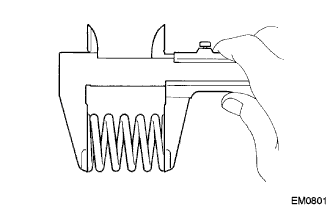
| 5. INSPECT INNER COMPRESSION SPRING |
Using a vernier caliper, measure the free length of the valve spring.
- Free length:
- 47.43 mm (1.867 in.)
 |
Using a steel set square, measure the deviation of the valve spring.
- Maximum deviation:
- 1.6 mm (0.063 in.)
 |
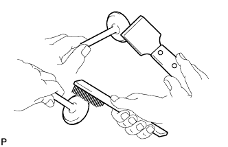
| 6. INSPECT INTAKE VALVE |
Using a gasket scraper, scrape off any carbon on the valve head.
 |
Using a vernier caliper, measure the overall length of the valve.
- Standard overall length:
- 101.71 mm (4.0043 in.)
- Minimum overall length:
- 101.21 mm (3.9846 in.)
 |
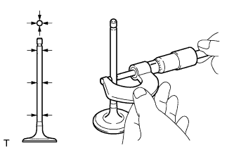
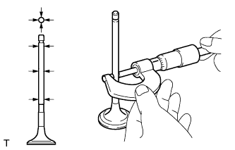
Using a micrometer, measure the diameter of the valve stem.
- Valve stem diameter:
- 5.470 to 5.485 mm (0.2154 to 0.2159 in.)
 |
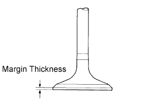
Using a vernier caliper, measure the valve head margin thickness.
- Standard margin thickness:
- 1.05 to 1.45 mm (0.0413 to 0.0571 in.)
- Minimum margin thickness:
- 0.50 mm (0.0197 in.)
 |
| 7. INSPECT EXHAUST VALVE |
Using a gasket scraper, scrape off any carbon on the valve head.
|
Using a vernier caliper, measure the overall length of the valve.
- Standard overall length:
- 101.15 mm (3.9823 in.)
- Minimum overall length:
- 100.70 mm (3.9646 in.)
 |
Using a micrometer, measure the diameter of the valve stem.
- Valve stem diameter:
- 5.465 to 5.480 mm (0.2152 to 0.2157 in.)
 |
Using a vernier caliper, measure the valve head margin thickness.
- Standard margin thickness:
- 1.20 to 1.60 mm (0.0472 to 0.0630 in.)
- Minimum margin thickness:
- 0.50 mm (0.0197 in.)
 |
| 8. INSPECT INTAKE VALVE GUIDE BUSH |
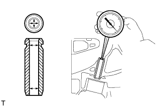
Using a caliper gauge, measure the inside diameter of the guide bush.
- Bushing inside diameter:
- 5.510 to 5.530 mm (0.2169 to 0.2177 in.)
 |
Subtract the valve stem diameter measurement from the guide bush inside diameter measurement.
- Standard oil clearance:
- 0.025 to 0.060 mm (0.0010 to 0.0024 in.)
- Maximum oil clearance:
- 0.090 mm (0.0035 in.)
| 9. INSPECT EXHAUST VALVE GUIDE BUSH |
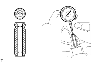
Using a caliper gauge, measure the inside diameter of the guide bush.
- Bushing inside diameter:
- 5.510 to 5.530 mm (0.2169 to 0.2177 in.)
 |
Subtract the valve stem diameter measurement from the guide bushing inside diameter measurement.
- Standard oil clearance:
- 0.030 to 0.065 mm (0.0012 to 0.0026 in.)
- Maximum oil clearance:
- 0.095 mm (0.0037 in.)
| 10. INSPECT VALVE LIFTER |
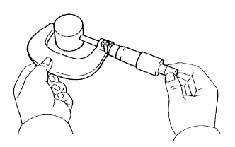
Using a micrometer, measure the lifter diameter.
- Lifter diameter:
- 30.966 to 30.976 mm (1.2191 to 1.2195 in.)
 |
Using a caliper gauge, measure the lifter bore diameter of the cylinder head.
- Standard lifter bore diameter:
- 31.009 to 31.025 mm (1.2208 to 1.2215 in.)
 |
Subtract the lifter diameter measurement from the lifter bore diameter measurement.
- Standard oil clearance:
- 0.033 to 0.059 mm (0.00130 to 0.00232 in.)
- Maximum oil clearance:
- 0.079 mm (0.00311 in.)
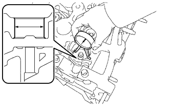
| 11. INSPECT CYLINDER HEAD SET BOLT |
Using a vernier caliper, measure the length of the head bolts from the seat to the end.
- Standard bolt length:
- 141.3 to 142.7 mm (5.563 to 5.618 in.)
- Maximum bolt length:
- 144.2 mm (5.677 in.)
 |