REMOVE LOWER INSTRUMENT PANEL FINISH PANEL LH (for Rear Disc Brake)
REMOVE LOWER INSTRUMENT PANEL FINISH PANEL RH (for Rear Disc Brake)
REMOVE CENTER NO. 1 INSTRUMENT CLUSTER FINISH PANEL ASSEMBLY (for Rear Disc Brake)
REMOVE UPPER CONSOLE PANEL SUB-ASSEMBLY (for Rear Disc Brake)
REMOVE PARKING BRAKE LEVER PROTECTOR LH (for Rear Disc Brake)
REMOVE PARKING BRAKE LEVER PROTECTOR RH (for Rear Disc Brake)
DISCONNECT NO. 3 PARKING BRAKE CABLE ASSEMBLY (for Rear Disc Brake)
DISCONNECT NO. 2 PARKING BRAKE CABLE ASSEMBLY (for Rear Disc Brake)
SEPARATE REAR DISC BRAKE CALIPER ASSEMBLY LH (for Rear Disc Brake)
SEPARATE REAR DISC BRAKE CALIPER ASSEMBLY RH (for Rear Disc Brake)
REMOVE REAR AXLE HUB AND BEARING ASSEMBLY LH (for Rear Drum Brake)
REMOVE REAR AXLE HUB AND BEARING ASSEMBLY RH (for Rear Drum Brake)
REMOVE REAR AXLE HUB AND BEARING ASSEMBLY LH (for Rear Disc Brake)
REMOVE REAR AXLE HUB AND BEARING ASSEMBLY RH (for Rear Disc Brake)
Rear Axle Beam -- Removal |
- NOTICE:
- For vehicles equipped with VSC, if the wheel alignment has been adjusted, and if suspension or underbody components have been removed/installed or replaced, be sure to perform the following initialization procedure in order for the system to function normally:
- Disconnect the cable from the negative (-) battery terminal for more than 2 seconds.
- Reconnect the cable to the negative (-) battery terminal.
- Perform zero point calibration of the yaw rate and acceleration sensor and test mode inspection.
| 1. DISCONNECT CABLE FROM NEGATIVE BATTERY TERMINAL |
| 2. REMOVE LOWER INSTRUMENT PANEL FINISH PANEL LH (for Rear Disc Brake) |
Disengage the 3 claws and clip, and then remove the lower instrument panel finish panel LH.
 |
| 3. REMOVE LOWER INSTRUMENT PANEL FINISH PANEL RH (for Rear Disc Brake) |
Disengage the 3 claws and clip, and then remove the lower instrument panel finish panel RH.
 |
| 4. REMOVE SHIFT LEVER KNOB SUB-ASSEMBLY (for Rear Disc Brake) |
- HINT:
- for Manual Transaxle (COROLLA_ZRE142 RM0000024DD08GX_01_0080.html).
- for Automatic Transaxle (COROLLA_ZRE142 RM0000024DD08GX_01_0184.html).
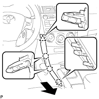
| 5. REMOVE CENTER NO. 1 INSTRUMENT CLUSTER FINISH PANEL ASSEMBLY (for Rear Disc Brake) |
- HINT:
- for Manual Transaxle (COROLLA_ZRE142 RM0000024DD08GX_01_0082.html).
- for Automatic Transaxle (COROLLA_ZRE142 RM0000024DD08GX_01_0185.html).
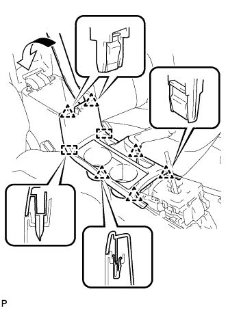
| 6. REMOVE UPPER CONSOLE PANEL SUB-ASSEMBLY (for Rear Disc Brake) |
Using a moulding remover, disengage the 6 clips and 2 guides, and remove the upper console panel sub-assembly.
 |
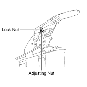
| 7. LOOSEN PARKING BRAKE CABLE (for Rear Disc Brake) |
Loosen the lock nut and adjusting nu to completely release the parking brake cable.
 |
| 8. REMOVE REAR WHEELS |
| 9. DRAIN BRAKE FLUID (for Rear Drum Brake) |
| 10. DISCONNECT REAR SPEED SENSOR WIRE LH (for Rear Drum Brake) |
Using a screwdriver, disconnect the connector from the rear speed sensor.
- NOTICE:
- Be careful not to damage the rear speed sensor.
 |
| 11. DISCONNECT REAR SPEED SENSOR WIRE RH (for Rear Drum Brake) |
- HINT:
- Perform the same procedure as the LH side.
| 12. DISCONNECT REAR SPEED SENSOR WIRE LH (for Rear Disc Brake) |
Using a screwdriver, disconnect the connector from the rear speed sensor.
- NOTICE:
- Be careful not to damage the rear speed sensor.
 |
| 13. DISCONNECT REAR SPEED SENSOR WIRE RH (for Rear Disc Brake) |
- HINT:
- Perform the same procedure as the LH side.
| 14. SEPARATE REAR SPEED SENSOR WIRE LH |
 |
Remove the bolt.
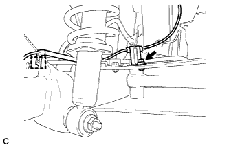
Disengage the clamp and separate the rear speed sensor wire from the rear axle beam.
| 15. SEPARATE REAR SPEED SENSOR WIRE RH |
- HINT:
- Perform the same procedure as the LH side.
| 16. SEPARATE NO. 3 PARKING BRAKE CABLE ASSEMBLY |
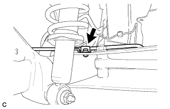 |
Remove the bolt and separate the No. 3 parking brake cable assembly.
| 17. SEPARATE NO. 2 PARKING BRAKE CABLE ASSEMBLY |
- HINT:
- Perform the same procedure as the No. 3 parking brake cable assembly.
| 18. REMOVE REAR BRAKE DRUM LH (for Rear Drum Brake) |
Release the parking brake and remove the rear brake drum.
- HINT:
- If the rear brake drum cannot be removed easily, perform the following procedure.
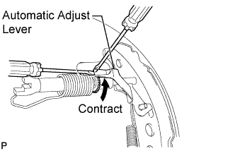
Remove the shoe adjusting hole plug and insert a screwdriver through the hole into the backing plate, and hold the automatic adjust lever away from the adjuster.
Using another screwdriver, contract the brake shoe by turning the adjusting bolt.
 |
| 19. REMOVE REAR BRAKE DRUM RH (for Rear Drum Brake) |
- HINT:
- Perform the same procedure as the LH side.
| 20. REMOVE PARKING BRAKE LEVER PROTECTOR LH (for Rear Disc Brake) |
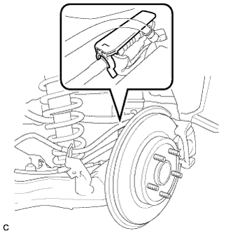
Remove the parking brake lever protector from the No. 3 parking brake cable assembly.
 |
| 21. REMOVE PARKING BRAKE LEVER PROTECTOR RH (for Rear Disc Brake) |
- HINT:
- Perform the same procedure as the LH side.
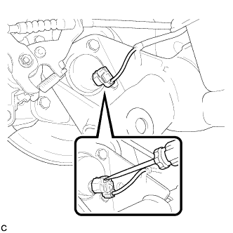
| 22. DISCONNECT NO. 3 PARKING BRAKE CABLE ASSEMBLY (for Rear Disc Brake) |
Separate the No. 3 parking brake cable assembly from the rear disc brake cylinder assembly.
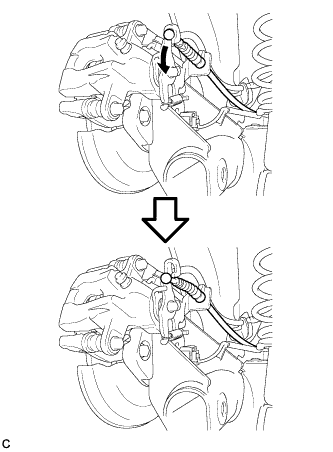 |
Remove the No. 3 parking brake cable assembly.
- HINT:
- Insert an offset wrench (14 mm) at the base of the No. 3 parking brake cable assembly as shown in the illustration to disengage the clip. Pull out the No. 3 parking brake cable assembly from the rear disc brake cylinder assembly.
 |
| 23. DISCONNECT NO. 2 PARKING BRAKE CABLE ASSEMBLY (for Rear Disc Brake) |
- HINT:
- Perform the same procedure as the No. 3 parking brake cable assembly.
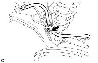
| 24. SEPARATE REAR FLEXIBLE HOSE LH (for Rear Disc Brake) |
Remove the bolt and separate the rear flexible hose LH from the rear axle beam.
 |
| 25. SEPARATE REAR FLEXIBLE HOSE RH (for Rear Disc Brake) |
- HINT:
- Perform the same procedure as the LH side.
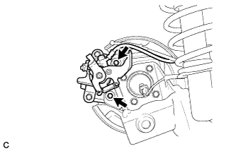
| 26. SEPARATE REAR DISC BRAKE CALIPER ASSEMBLY LH (for Rear Disc Brake) |
Remove the 2 bolts, and separate the rear disc brake caliper assembly.
- NOTICE:
- Use wire or an equivalent tool to keep the brake caliper from hanging down by the flexible hose.
 |
| 27. SEPARATE REAR DISC BRAKE CALIPER ASSEMBLY RH (for Rear Disc Brake) |
- HINT:
- Perform the same procedure as the LH side.
| 28. REMOVE REAR DISC LH (for Rear Disc Brake) |
Remove the rear disc.
- HINT:
- Place matchmarks on the disc and axle hub.
 |
| 29. REMOVE REAR DISC RH (for Rear Disc Brake) |
- HINT:
- Perform the same procedure as the LH side.
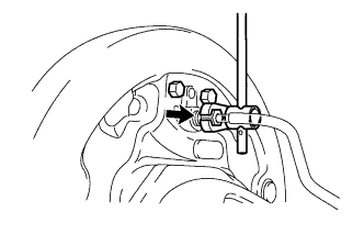
| 30. SEPARATE REAR FLEXIBLE HOSE LH (for Rear Drum Brake) |
Using a union nut wrench (10 mm), separate the No. 4 rear brake tube while holding the rear flexible hose with a wrench.
- NOTICE:
- Do not bend or damage the brake line.
- Do not allow any foreign matter such as dirt and dust to enter the brake line from the clip or bracket.
 |
Remove the clip and disconnect the rear flexible hose LH.
| 31. SEPARATE REAR FLEXIBLE HOSE RH (for Rear Drum Brake) |
- HINT:
- Perform the same procedure as the LH side.
| 32. REMOVE NO. 4 REAR BRAKE TUBE (for Rear Drum Brake) |
Using a union nut wrench (10 mm), remove the No. 4 rear brake tube.
 |
| 33. REMOVE NO. 3 REAR BRAKE TUBE (for Rear Drum Brake) |
- HINT:
- Perform the same procedure as the No. 4 rear brake tube.
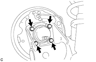
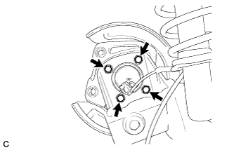
| 34. REMOVE REAR AXLE HUB AND BEARING ASSEMBLY LH (for Rear Drum Brake) |
Remove the 4 bolts and the rear axle hub and bearing assembly.
 |
| 35. REMOVE REAR AXLE HUB AND BEARING ASSEMBLY RH (for Rear Drum Brake) |
- HINT:
- Perform the same procedure as the LH side.
| 36. REMOVE REAR AXLE HUB AND BEARING ASSEMBLY LH (for Rear Disc Brake) |
Remove the 4 bolts and the rear axle hub and bearing assembly.
 |
| 37. REMOVE REAR AXLE HUB AND BEARING ASSEMBLY RH (for Rear Disc Brake) |
- HINT:
- Perform the same procedure as the LH side.
| 38. REMOVE REAR AXLE BEAM DAMPER |
Remove the rear axle beam damper.
 |
| 39. REMOVE REAR STABILIZER BAR |
Remove the 2 bolts, 2 nuts and rear stabilizer bar.
- NOTICE:
- Be sure to loosen the nuts.
 |
| 40. SEPARATE REAR SHOCK ABSORBER WITH COIL SPRING LH |
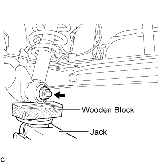 |
Support the rear axle beam assembly using a jack and wooden block.
- NOTICE:
- Do not excessively jack up the rear axle beam assembly.
Remove the nut and rear No. 1 shock absorber retainer.
Separate the rear shock absorber with coil spring LH (lower side).
| 41. SEPARATE REAR SHOCK ABSORBER WITH COIL SPRING RH |
- HINT:
- Perform the same procedure as the LH side.
| 42. REMOVE REAR AXLE BEAM ASSEMBLY |
Support the rear axle beam assembly using 2 jacks and 2 wooden blocks.
 |
Remove the 2 bolts, 2 nuts, and rear axle beam assembly.
- NOTICE:
- Since stopper nuts are used, loosen the bolts.
 |
| 43. REMOVE REAR AXLE CARRIER BUSHING LH |
Place matchmarks on the 2 notches of the rear axle carrier bushing and rear axle beam assembly.
 |
Using a chisel and hammer, bend the 2 portions of the rear axle carrier bushing rib.
- NOTICE:
- When removing the rear axle carrier bushing, do not erase the matchmarks on the rear axle beam assembly.
- If the axle beam has been scratched, apply the paint to the axle beam assembly.
Using SST, remove the rear axle carrier bushing from the rear axle beam assembly.
- SST
- 09950-40011(09951-04020,09952-04010,09953-04030,09954-04020,09955-04051,09957-04010,09958-04011)
09950-60010(09951-00630)
| 44. REMOVE REAR AXLE CARRIER BUSHING RH |
- HINT:
- Perform the same procedure as the LH side.