Dtc B1412 Ambient Temperature Sensor Circuit
DESCRIPTION
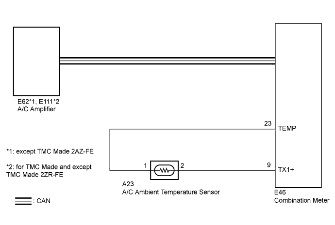
WIRING DIAGRAM
INSPECTION PROCEDURE
CHECK CAN COMMUNICATION SYSTEM
READ VALUE USING TECHSTREAM
CHECK HARNESS AND CONNECTOR (AMBIENT TEMPERATURE SENSOR CIRCUIT)
INSPECT COMBINATION METER
INSPECT AMBIENT TEMPERATURE SENSOR
DTC B1412 Ambient Temperature Sensor Circuit |
DESCRIPTION
The ambient temperature sensor is installed in front of the condenser. This sensor detects the temperature outside the cabin and sends the appropriate signals to the A/C amplifier via the CAN communication system.DTC No.
| DTC Detection Condition
| Trouble Area
|
B1412
| Open or short in ambient temperature sensor circuit
| - Ambient temperature sensor
- Harness or connector between ambient temperature sensor and combination meter
- Combination meter
- A/C amplifier
- CAN communication system
|
WIRING DIAGRAM
INSPECTION PROCEDURE
| 1.CHECK CAN COMMUNICATION SYSTEM |
Use the Techstream to check if the CAN communication system is functioning normally.
- Result:
Result
| Proceed to
|
CAN DTC is not output
| A
|
CAN DTC is output
| B
|
| 2.READ VALUE USING TECHSTREAM |
Connect the Techstream to the DLC3.
Turn the ignition switch to ON.
Turn the Techstream on.
Enter the following menus: Body Electrical / Air Conditioner / Data List.
Check the value(s) by referring to the table below.
Air ConditionerTester Display
| Measurement Item/Range
| Normal Condition
| Diagnostic Note
|
Ambient Temp Sensor
(Ambi Temp Sens)
| Ambient temperature sensor / Min: -23.3°C (-9.94°F), Max: 65.95°C (150.71°F)
| Actual ambient temperature displayed
| Open in circuit: -23.3°C (-9.94°F)
Short in circuit: 65.95°C (150.71°F)
|
- OK:
- The display is as specified in the "Normal Condition" column.
- Result:
Result
| Proceed to
|
NG
| A
|
OK (When troubleshooting according to Problem Symptoms Table)
| B
|
OK (When troubleshooting according to the DTC output)
| C
|
| 3.CHECK HARNESS AND CONNECTOR (AMBIENT TEMPERATURE SENSOR CIRCUIT) |
Disconnect the connector from the combination meter.
Measure the resistance according to the value(s) in the table below.
- Standard Resistance:
Tester Connection
| Condition
| Specified Condition
|
E46-9 (TX1+) - E46-23 (TEMP)
| 25°C (77°F)
| 1.60 to 1.80 kΩ
|
E46-9 (TX1+) - E46-23 (TEMP)
| 40°C (104°F)
| 0.80 to 1.00 kΩ
|
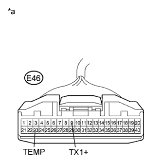
Text in Illustration*a
| Front view of wire harness connector
(to Combination Meter)
|
| 4.INSPECT COMBINATION METER |
Temporarily replace the combination meter with a known good one (COROLLA_ZRE142 RM0000024D7032X.html).
- HINT:
- Since the combination meter cannot be inspected while it is removed from the vehicle, replace the combination meter with a known good one and check that the condition returns to normal.
Check for DTCs.
- Result:
Result
| Proceed to
|
DTC B1412 is not output
| A
|
DTC B1412 is output
| B
|
| 5.INSPECT AMBIENT TEMPERATURE SENSOR |
Remove the ambient temperature sensor.
Disconnect the connector from the ambient temperature sensor.
Measure the resistance according to the value(s) in the table below.
- Standard Resistance:
Tester Connection
| Condition
| Specified Condition
|
A23-1 - A23-2
| 10°C (50°F)
| 3.00 to 3.73 kΩ
|
A23-1 - A23-2
| 15°C (59°F)
| 2.45 to 2.88 kΩ
|
A23-1 - A23-2
| 20°C (68°F)
| 1.95 to 2.30 kΩ
|
A23-1 - A23-2
| 25°C (77°F)
| 1.60 to 1.80 kΩ
|
A23-1 - A23-2
| 30°C (86°F)
| 1.28 to 1.47 kΩ
|
A23-1 - A23-2
| 35°C (95°F)
| 1.00 to 1.22 kΩ
|
A23-1 - A23-2
| 40°C (104°F)
| 0.80 to 1.00 kΩ
|
A23-1 - A23-2
| 45°C (113°F)
| 0.65 to 0.85 kΩ
|
A23-1 - A23-2
| 50°C (122°F)
| 0.50 to 0.70 kΩ
|
A23-1 - A23-2
| 55°C (131°F)
| 0.44 to 0.60 kΩ
|
A23-1 - A23-2
| 60°C (140°F)
| 0.36 to 0.50 kΩ
|
- NOTICE:
- Hold the sensor only by its connector. Touching the sensor may change the resistance value.
- When measuring, the sensor temperature must be the same as the ambient temperature.
- HINT:
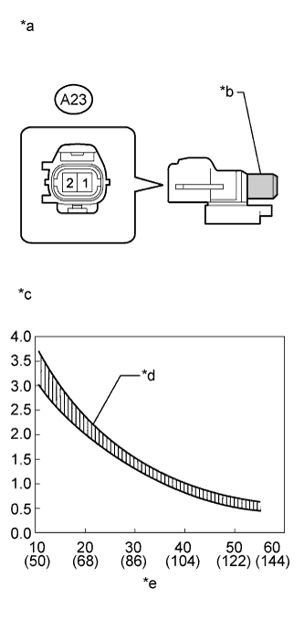
- As the temperature increases, the resistance decreases (see the graph).
Text in Illustration*a
| Component without harness connected
(Ambient Temperature Sensor)
|
*b
| Sensing Portion
|
*c
| Resistance (kΩ)
|
*d
| Allowable Range
|
*e
| Temperature (°C (°F))
|
| OK |
|
|
|
| REPAIR OR REPLACE HARNESS OR CONNECTOR (AMBIENT TEMPERATURE SENSOR - COMBINATION METER) |
|