Sfi System -- Data List / Active Test |
| DATA LIST |
- HINT:
- Using the Techstream to read the Data List allows the values or states of switches, sensors, actuators and other items to be read without removing any parts. This non-intrusive inspection can be very useful because intermittent conditions or signals may be discovered before parts or wiring is disturbed. Reading the Data List information early in troubleshooting is one way to save diagnostic time.
- NOTICE:
- In the table below, the values listed under Normal Condition are reference only. Do not depend solely on these values when determining whether or not a part is faulty.
Warm up the engine.
Turn the ignition switch off.
Connect the Techstream to the DLC3.
Turn the ignition switch to ON.
Turn the Techstream on.
Enter the following menus: Powertrain / Engine and ECT / Data List.
According to the display on the Techstream, read the Data List.
| Tester Display | Measurement Item/Range | Normal Condition*1 | Diagnostic Note |
| Vehicle Speed | Vehicle speed: Min.: 0 mph (0 km/h), Max.: 158 mph (255 km/h) | Actual vehicle speed | Speed indicated on speedometer |
| Engine Speed | Engine speed: Min.: 0 rpm, Max.: 16383 rpm | 650 to 750 rpm: Idling (Automatic transaxle) 600 to 700 rpm: Idling (Manual transaxle) | - |
| Calculate Load | Calculated load by ECM: Min.: 0%, Max.: 100% |
| - |
| Vehicle Load | Vehicle load: Min.: 0%, Max.: 25700% | Actual vehicle load | Load percentage in terms of maximum intake air flow amount |
| MAF | Air flow rate from mass air flow meter: Min.: 0 gm/s, Max.: 655.35 gm/s | 1 to 3 gm/s: Idling 5 to 10 gm/s: Running without load (3000 rpm) | If value approximately 0.0 gm/s:
|
| Atmosphere Pressure | Atmospheric pressure: Min.: 0 kPa (0 mmHg) , Max.: 255 kPa (1912 mmHg) | Equivalent to atmospheric pressure | - |
| Coolant Temp | Engine coolant temperature: Min.: -40°C (-40°F), Max.: 140°C (284°F) | 75 to 100°C (167 to 212°F): After warming up |
|
| Intake Air | Intake air temperature: Min.: -40°C (-40°F), Max.: 140°C (284°F) | Equivalent to ambient air temperature |
|
| Engine Run Time | Engine run time: Min.: 0 s, Max.: 65535 s | Time since engine started | - |
| Initial Engine Coolant Temp | Initial engine coolant temperature: Min.: -40°C (-40°F), Max.: 119.3°C (246.7°F) | Coolant temperature when engine started | - |
| Initial Intake Air Temp | Initial intake air temperature: Min.: -40°C (-40°F), Max.: 119.3°C (246.7°F) | Intake air temperature when engine started | - |
| Battery Voltage | Battery voltage: Min.: 0 V, Max.: 65.535 V | 11 to 14 V: Idling | - |
| Glow Indicator Supported | Glow indicator supported: Supported or Unsupported | - | - |
| Glow Indicator | Glow indicator: ON or OFF | - | - |
| Accelerator Position | Accelerator pedal position: Min.: 0%, Max.: 399.9% | Actual accelerator pedal position | - |
| Accel Sens. No. 1 Volt % | Accelerator pedal position No. 1: Min.: 0%, Max.: 100% | 10 to 22%: Accelerator pedal fully released 52 to 90%: Accelerator pedal fully depressed | - |
| Accel Sens. No. 2 Volt % | Accelerator pedal position No. 2: Min.: 0%, Max.: 100% | 24 to 40%: Accelerator pedal fully released 68 to 95%: Accelerator pedal fully depressed | - |
| Accel Sensor Out No. 1 | Accelerator pedal position sensor No. 1 voltage: Min.: 0 V, Max.: 4.98 V | 0.5 to 1.1 V: Accelerator pedal fully released 2.6 to 4.5 V: Accelerator pedal fully depressed | - |
| Accel Sensor Out No. 2 | Accelerator pedal position sensor No. 2 voltage: Min.: 0 V, Max.: 4.98 V | 1.2 to 2.0 V: Accelerator pedal fully released 3.4 to 4.75 V: Accelerator pedal fully depressed | - |
| Accelerator Idle Position | Whether or not accelerator pedal position sensor detecting idle: ON or OFF | ON: Idling | - |
| Accel Fully Close Learn #1 | Accelerator fully closed learning value No. 1: Min.: 0 deg, Max.: 124.5 deg | - | Electronic throttle control system service data |
| Accel Fully Close Learn #2 | Accelerator fully closed learning value No. 2: Min.: 0 deg., Max.: 124.5 deg. | - | Electronic throttle control system service data |
| Throttle Sensor Volt % | Throttle valve opening percentage according to throttle position sensor: Min.: 0%, Max.: 100% |
| Value calculated based on the voltage at terminal VTA1 |
| Throttl Sensor #2 Volt % | Throttle valve opening percentage according to throttle position sensor No. 2: Min.: 0%, Max.: 100% |
| Value calculated based on the voltage at terminal VTA2 |
| ST1 | Brake pedal signal: ON or OFF | ON: Brake pedal released | - |
| System Guard | System guard: ON or OFF | - | - |
| Open Side Malfunction | Open side malfunction: ON or OFF | - | - |
| Throttle Idle Position | Whether or not throttle position sensor detecting idle: ON or OFF |
| - |
| Throttle Require Position | Required position: Min.: 0 V, Max.: 4.98 V | 0.5 to 1.1 V: Idling | - |
| Throttle Sensor Position*3 | Throttle sensor positioning: Min.: 0%, Max.: 100% |
| Recognition value for throttle opening angle on ECM |
| Throttle Position No. 1 | Throttle position No. 1: Min.: 0 V, Max.: 4.98 V |
| - |
| Throttle Position No. 2 | Throttle position No. 2: Min.: 0 V, Max.: 4.98 V |
| - |
| Throttle Position Command | Throttle position command value: Min.: 0 V, Max.: 4.980 V | 0.5 to 4.8 V | - |
| Throttle Sens Open Pos #1 | Throttle sensor opener position No. 1: Min.: 0 V, Max.: 4.980 V | 0.6 to 1.4 V | Electronic throttle control system service data |
| Throttle Sens Open Pos #2 | Throttle sensor opener position No. 2: Min.: 0 V, Max.: 4.980 V | 1.7 to 2.5 V | Electronic throttle control system service data |
| Throttle Motor Current | Throttle actuator current: Min.: 0 A, Max.: 19.9 A | 0 to 3.0 A: Idling | Electronic throttle control system service data |
| Throttle Motor DUTY | Throttle actuator: Min.: 0%, Max.: 100% | 10 to 22%: Idling after engine warmed up | Electronic throttle control system service data |
| Throttle Motor Duty (Open) | Throttle actuator duty ratio (open): Min.: 0%, Max.: 255% | 0 to 40%: Idling | Electronic throttle control system service data |
| Throttle Motor Duty (Close) | Throttle actuator duty ratio (close): Min.: 0%, Max.: 255% | 0 to 40%: Idling | Electronic throttle control system service data |
| Throttle Fully Close Learn | Throttle valve fully closed (learned value): Min.: 0 V, Max.: 4.98 V | 0.4 to 1.0 V: Accelerator pedal released | - |
| +BM Voltage | +BM voltage: Min.: 0, Max.: 79.998 V | 11 to 14 V: Ignition switch ON and system normal | Electronic throttle control system service data |
| Actuator Power Supply | Actuator power supply: ON or OFF | ON: Idling | - |
| Throttle Position | Throttle valve opening angle: Min.: 0 deg, Max.: 499.99 deg | - | When the engine stalls, is difficult to start, or idles roughly |
| ISC Flow | Flow rate calculated from information from each sensor: Min.: 0 L/s, Max.: 79.99 L/s | - | When the engine stalls, is difficult to start, or idles roughly |
| ISC Position | Target valve opening angle calculated from ISC: Min.: 0 deg, Max.: 499.99 deg | - | This is the throttle valve opening amount while the engine is idling (the throttle valve opening amount necessary to maintain ISC air flow). |
| ISC Feedback Value | ISC feedback value: Min.: -40 L/s, Max.: 39.99 L/s | - | When the engine stalls, is difficult to start, or idles roughly |
| ISC Learning Value | ISC learning value: Min.: -40 L/s, Max.: 39.99 L/s | - | When the engine stalls, is difficult to start, or idles roughly |
| Electric Load Feedback Val | Electrical load feedback value: Min.: -40 L/s, Max.: 39.99 L/s | - | When the engine stalls, is difficult to start, or idles roughly |
| Air Conditioner FB Val | Air conditioner load feedback value: Min.: -40 L/s, Max.: 39.99 L/s | - | When the engine stalls, is difficult to start, or idles roughly |
| Low Revolution Control | Status of low engine speed control: ON or OFF | - | When the engine stalls, is difficult to start, or idles roughly |
| N Range Status*3 | Judgment shift lever N position: Min.: -40 L/s, Max.: 39.99 L/s | - | When the engine stalls, is difficult to start, or idles roughly |
| Eng Stall Control FB Flow | Feedback value of intake air flow: Min.: -40 L/s, Max.: 39.99 L/s | - | When the engine stalls, is difficult to start, or idles roughly |
| Deposit Loss Flow | Deposit loss air flow rate: Min.: -40 L/s, Max.: 39.99 L/s | - |
|
| Injector (Port) | Injection duration for cylinder 1: Min.: 0 μs, Max.: 65535 μs | 1000 to 3000 μs: Idling | - |
| Injection Volum (Cylinder1) | Injection volume (Cylinder 1): Min.: 0 ml, Max.: 2.047 ml | 0.05 to 0.15 ml: Idling | Quantity of fuel injection volume for 10 times |
| Fuel Pump/Speed Status | Fuel pump/status: ON or OFF | - | - |
| Vacuum Pump*5 | Key-off EVAP system leak detection pump status: ON or OFF | - | - |
| Current Fuel Type | Current fuel type | Gasoline/petrol | - |
| EVAP (Purge) VSV | EVAP (Purge) VSV control duty: Min.: 0%, Max.: 100% | 10 to 50%: Idling, under purge control | Order signal from ECM |
| Evap Purge Flow | Ratio of evaporative purge flow to intake air volume: Min.: 0%, Max.: 399.9% | 0 to 10%: Idling | - |
| Purge Density Learn Value | Learning value of purge density: Min.: -200, Max.: 199.993 | -40 to 10: Idling | - |
| Vapor Pressure Pump | Vapor pressure: Min.: 0 kPa (0 mmHg), Max.: 1441.77 kPa (10814.71 mmHg) | Approximately 100 kPa (760 mmHg) (absolute): Ignition switch ON | EVAP system pressure monitored by canister pressure sensor |
| Vapor Pressure (Calculated) | Vapor pressure (calculated): Min.: -720.896 kPa (-5407.441 mmHg), Max.: 720.874 kPa (5407.276 mmHg) | Approximately 100 kPa (760 mmHg) (absolute): Ignition switch ON | EVAP system pressure monitored by canister pressure sensor |
| EVAP System Vent Valve*5 | Key-off EVAP system vent valve status: ON or OFF | - | - |
| EVAP Purge VSV | VSV status for EVAP control: ON or OFF | - | - |
| Purge Cut VSV Duty | Purge cut VSV duty: Min.: 0%, Max.: 399.9% | - | - |
| Target Air-Fuel Ratio | Ratio compared to stoichiometric level: Min.: 0, Max.: 1.999 | 0.8 to 1.2: Idling | - |
| AF Lambda B1S1 | Short-term fuel trim associated with bank 1 sensor 1: Min.: 0, Max.: 1.99 |
| - |
| AFS Voltage B1S1 | Air fuel ratio sensor output voltage for bank 1 sensor 1: Min.: 0 V, Max.: 7.99 V | 2.6 to 3.8 V: Idling, engine warmed up | Performing Control the Injection Volume or Control the Injection Volume for A/F Sensor function of Active Test enables technician to check output voltage of sensors |
| AFS Current B1S1 | Air fuel ratio sensor output current for bank 1 sensor 1: Min.: -128 mA, Max.: 127.99 mA | -0.5 to 0.5 mA: Idling, engine warmed up | Value becomes higher when fuel-cut executed under high engine speed |
| A/F Heater Duty #1 | Air fuel ratio heater duty for bank 1: Min.: 0%, Max.: 399.9% | 0 to 100% | - |
| O2S B1S2 | Heated oxygen sensor output voltage for bank 1 sensor 2: Min.: 0 V, Max.: 1.275 V | 0.0 to 0.9 V: Driving at 43 mph (70 km/h) | Performing Control the Injection Volume or Control the Injection Volume for A/F Sensor function of Active Test enables technician to check output voltage of sensors |
| O2S Impedance B1S2 | Sub heated oxygen sensor impedance (bank 1 sensor 2): Min.: 0 ohm, Max.: 21247.67 ohm | 5 to 15000 ohm: After driving for 10 minutes or more in urban area | - |
| O2 Heater B1S2 | Heated oxygen sensor heater for bank 1 sensor 2: Not Act or Active | - | - |
| O2 Heater Curr Val B1S2 | Heated oxygen sensor current for bank 1 sensor 2: Min.: 0 A, Max.: 4.999 A | - | - |
| Short FT #1 | Short-term fuel trim of bank 1: Min.: -100%, Max.: 99.2% | -15 to 15% | Short-term fuel compensation used to maintain air fuel ratio at stoichiometric air fuel ratio |
| Long FT #1 | Long-term fuel trim of bank 1: Min.: -100%, Max.: 99.2% | -15 to 15% |
|
| A/F Learn Value Idle #1 | Air fuel ratio learn value of idle area (bank 1): Min.: -50%, Max.: 49.6% | -15 to 15% | Learning is performed when idling with the engine warmed up (engine coolant temperature is 80°C [176°F]) or higher. |
| A/F Learn Value Low #1 | Air fuel ratio learn value of low load area (bank 1): Min.: -50%, Max.: 49.6% | -15 to 15% | Learning is performed when driving with the engine warmed up (engine coolant temperature is 80°C [176°F] or higher) and operating in the low load range (when the range of engine loads is divided into four parts) |
| A/F Learn Value Mid1 #1 | Air fuel ratio learn value of middle1 load area (bank 1): Min.: -50%, Max.: 49.6% | -15 to 15% | Learning is performed when driving with the engine warmed up (engine coolant temperature is 80°C [176°F] or higher) and operating in the mid-size load range closer to the low load range (when the range of engine loads is divided into four parts). |
| A/F Learn Value Mid2 #1 | Air fuel ratio learn value of middle2 load area (bank 1): Min.: -50%, Max.: 49.6% | -15 to 15% | Learning is performed when driving with the engine warmed up (engine coolant temperature is 80°C [176°F] or higher) and operating in the mid-size load range closer to the high load range (when the range of engine loads is divided into four parts). |
| A/F Learn Value High #1 | Air fuel ratio learn value of high load area (bank 1): Min.: -50%, Max.: 49.6% | -15 to 15% | Learning is performed when driving with the engine warmed up (engine coolant temperature is 80°C [176°F] or higher) and operating in the high load range (when the range of engine loads is divided into four parts). |
| Total FT #1 | Total fuel trim of bank 1 Average value for fuel trim system of bank 1: Min.: -0.5, Max.: 0.496 | -0.28 to 0.2: Idling | - |
| Fuel System Status #1 | Fuel system status (bank 1): OL, CL, OLDrive, OLFault, CLFault or Unused | CL: Idling after warming up |
|
| Fuel System Status #2 | Fuel system status (bank 2): OL, CL, OLDrive, OLFault, CLFault or Unused | Unused |
|
| IGN Advance | Ignition timing advance for No. 1 cylinder: Min.: -64 deg., Max.: 63.5 deg. | 0 to 15 deg.: Idling | - |
| Knock Feedback Value | Feedback value of knocking: Min.: -1024 deg(CA), Max.: 1023.9 deg(CA) | -20 to 0 deg(CA): Driving at 44 mph (70 km/h) | - |
| Knock Correct Learn Value | Correction learning value of knocking: Min.: -1024 deg(CA), Max.: 1023.9 deg(CA) | 0 to 20 deg(CA): Driving at 44 mph (70 km/h) | - |
| Idle Spark Advn Ctrl #1 | Ignition timing advance value (for No. 1 cylinder): Min.: 0 deg(CA), Max.: 15.93 deg(CA) | - | When the engine stalls, is difficult to start, or idles roughly |
| Idle Spark Advn Ctrl #2 | Ignition timing advance value (for No. 2 cylinder): Min.: 0 deg(CA), Max.: 15.93 deg(CA) | - | When the engine stalls, is difficult to start, or idles roughly |
| Idle Spark Advn Ctrl #3 | Ignition timing advance value (for No. 3 cylinder): Min.: 0 deg(CA), Max.: 15.93 deg(CA) | - | When the engine stalls, is difficult to start, or idles roughly |
| Idle Spark Advn Ctrl #4 | Ignition timing advance value (for No. 4 cylinder): Min.: 0 deg(CA), Max.: 15.93 deg(CA) | - | When the engine stalls, is difficult to start, or idles roughly |
| VVT Control Status #1 | VVT control (bank 1) status: ON or OFF | - | - |
| VVT Advance Fail | Status of VVT advance fail: ON or OFF | ON: VVT control failure | - |
| VVT Aim Angle #1*2 | VVT aim angle (bank 1): Min.: 0%, Max.: 399.9% | - | VVT duty signal value during intrusive operation |
| VVT Change Angle #1*2 | VVT change angle (bank 1): Min.: 0 DegFR, Max.: 639.9 DegFR | - | Displacement angle during intrusive operation |
| VVT OCV Duty #1*2 | VVT camshaft timing oil control valve operation duty: Min.: 0%, Max.: 399.9% | - | Requested duty value for intrusive operation |
| VVT Ex Hold Lrn Val #1*2 | VVT exhaust hold duty ratio learning value (bank 1): Min.: 0%, Max.: 399.9% | - | VVT duty signal value during intrusive operation |
| VVT Ex Chg Angle #1*2 | VVT exhaust change angle (bank 1): Min.: 0 DegFR, Max.: 639.9 DegFR | - | Displacement angle during intrusive operation (Active Test) |
| VVT Ex OCV Duty #1*2 | VVT exhaust camshaft timing oil control valve duty (bank 1): Min.: 0%, Max.: 399.9% | - | Requested duty value for intrusive operation (Active Test) |
| VN Turbo Type | Variable nozzle turbo type: Not Avl or Commo or Vacuum or CAN Com | Not Avl (Unused) | - |
| Catalyst Temp B1S1 | Catalyst temperature (associated with sensor 1): Min.: -40°C (-40°F), Max.: 6513.5°C (11756.3°F) | Close to catalyst inlet temperature | - |
| Catalyst Temp B1S2 | Catalyst temperature (associated with sensor 2): Min.: -40°C (-40°F), Max.: 6513.5°C (11756.3°F) | Close to catalyst outlet temperature | - |
| Starter Signal | Starter signal (STA terminal input status): Open or Close | Open: Cranking | - |
| Starter Control | Ignition switch signal (STSW terminal input status): ON or OFF | ON: Cranking (during ignition switch operation) | - |
| Power Steering Signal | Power steering signal: ON or OFF | ON: Power steering operation | - |
| Starter Relay | Starter relay (STAR terminal output status): ON or OFF | ON: Cranking | - |
| ACC Relay | ACC (cut) relay (ACCR terminal output status): ON or OFF | ON: Cranking | - |
| Neutral Position SW Signal*3 | Park/Neutral position switch status: ON or OFF | ON: P or N position | - |
| Clutch Switch*4 | Clutch switch status: ON or OFF | ON: Clutch pedal depressed | - |
| Clutch Start SW*4 | Clutch start switch status: ON or OFF | ON: Clutch pedal depressed | - |
| Stop Light Switch | Stop light switch status: ON or OFF | ON: Brake pedal depressed | - |
| A/C Signal | Air conditioning signal: ON or OFF | ON: Air conditioning ON | - |
| Closed Throttle Position SW | Closed throttle position switch: ON or OFF |
| - |
| Fuel Cut Condition | Fuel cut determination flag: ON or OFF | - | - |
| Immobiliser Communication | Immobiliser communication: ON or OFF | ON: Normal | - |
| Check Mode | Check mode: ON or OFF | ON: Check mode ON | (COROLLA_ZRE142 RM000000PDL0PIX.html) |
| SPD Test Result | Check mode result for vehicle speed sensor: Compl or Incmpl | - | - |
| Misfire Test Result | Check mode result for misfire monitor: Compl or Incmpl | - | - |
| OXS1 Test Result | Check mode result for heated oxygen sensor (bank 1): Compl or Incmpl | - | - |
| A/F Test Results #1 | Check mode result for air fuel ratio sensor (bank 1) Compl or Incmpl | - | - |
| Complete Parts Monitor | Comprehensive component monitor: Not Avl or Avail | - | - |
| Fuel System Monitor | Fuel system monitor: Not Avl or Avail | - | - |
| Misfire Monitor | Misfire monitor: Not Avl or Avail | - | - |
| EGR/VVT Monitor | EGR monitor: Not Avl or Avail | - | - |
| EGR/VVT Monitor | EGR monitor: Compl or Incmpl | - | - |
| O2S(A/FS) Heater Monitor | O2S (A/FS) heater monitor: Not Avl or Avail | - | - |
| O2S(A/FS) Heater Monitor | O2S (A/FS) heater monitor: Compl or Incmpl | - | - |
| O2S(A/FS) Monitor | O2S (A/FS) monitor: Not Avl or Avail | - | - |
| O2S(A/FS) Monitor | O2S (A/FS) monitor: Compl or Incmpl | - | - |
| A/C Monitor | A/C monitor: Not Avl or Avail | - | - |
| A/C Monitor | A/C monitor: Compl or Incmpl | - | - |
| 2nd Air Monitor | 2nd air monitor: Not Avl or Avail | - | - |
| 2nd Air Monitor | 2nd air monitor: Compl or Incmpl | - | - |
| EVAP Monitor | EVAP monitor: Not Avl or Avail | - | - |
| EVAP Monitor | EVAP monitor: Compl or Incmpl | - | - |
| Heated Catalyst Monitor | Heated catalyst monitor: Not Avl or Avail | - | - |
| Heated Catalyst Monitor | Heated catalyst monitor: Compl or Incmpl | - | - |
| Catalyst Monitor | Catalyst monitor: Not Avl or Avail | - | - |
| Catalyst Monitor | Catalyst monitor: Compl or Incmpl | - | - |
| Component Monitor ENA | Comprehensive component monitor: Unable or Enable | - | - |
| Component Monitor CMPL | Comprehensive component monitor: Compl or Incmpl | - | - |
| Fuel System Monitor ENA | Fuel system monitor: Unable or Enable | - | - |
| Fuel System Monitor CMPL | Fuel system monitor: Compl or Incmpl | - | - |
| Misfire Monitor ENA | Misfire monitor: Unable or Enable | - | - |
| Misfire Monitor CMPL | Misfire monitor: Compl or Incmpl | - | - |
| EGR/VVT Monitor ENA | EGR monitor: Unable or Enable | - | - |
| EGR/VVT Monitor CMPL | EGR monitor: Compl or Incmpl | - | - |
| Heater Monitor ENA | O2S (A/FS) heater monitor: Unable or Enable | - | - |
| Heater Monitor CMPL | O2S (A/FS) heater monitor: Compl or Incmpl | - | - |
| O2S(A/FS) Monitor ENA | O2S (A/FS) monitor: Unable or Enable | - | - |
| O2S(A/FS) Monitor CMPL | O2S (A/FS) monitor: Compl or Incmpl | - | - |
| A/C Monitor ENA | A/C monitor: Unable or Enable | - | - |
| A/C Monitor CMPL | A/C monitor: Compl or Incmpl | - | - |
| 2nd Air Monitor ENA | 2nd air monitor: Unable or Enable | - | - |
| 2nd Air Monitor CMPL | 2nd air monitor: Compl or Incmpl | - | - |
| EVAP Monitor ENA | EVAP monitor: Unable or Enable | - | - |
| EVAP Monitor CMPL | EVAP monitor: Compl or Incmpl | - | - |
| Heated Cat Monitor ENA | Heated catalyst monitor: Unable or Enable | - | - |
| Heated Cat Monitor CMPL | Heated catalyst monitor: Compl or Incmpl | - | - |
| Catalyst Monitor ENA | Catalyst monitor: Unable or Enable | - | - |
| Catalyst Monitor CMPL | Catalyst monitor: Compl or Incmpl | - | - |
| TC Terminal | TC terminal status: ON or OFF | - | - |
| # Codes(Include History) | Number of emission related DTCs | 0: No emission related DTC detected | - |
| MIL | MIL status: ON or OFF | ON: MIL ON | - |
| MIL ON Run Distance | Distance traveled since MIL turned ON: Min.: 0 Km (0 mile), Max.: 65535 Km (40645 mile) | Distance since DTC detected | - |
| Running Time from MIL ON | Running time since MIL turned ON: Min.: 0 min, Max.: 65535 min | Equivalent to running time since MIL turned ON | - |
| Time after DTC Cleared | Time since DTCs cleared: Min.: 0 min, Max.: 65535 min | Equivalent to time since DTCs cleared | - |
| Distance from DTC Cleared | Distance traveled since DTCs cleared: Min.: 0 km (0 mile), Max.: 65535 km (40723 mile) | Equivalent to distance driven since DTCs cleared | - |
| Warmup Cycle Cleared DTC | Warm-up cycles since DTCs cleared: Min.: 0, Max.: 255 | - | Number of warm-up cycles since DTCs cleared |
| Dist Batt Cable Disconnect | Accumulated distance from battery cable disconnected: Min.: 0 Km (0 mile), Max.: 65535 Km (40723 mile) | - | - |
| IG OFF Elapsed Time*4 | Cumulative time after ignition switch off: Min.: 0 min, Max.: 655350 min | - | - |
| OBD Requirements | OBD requirement | OBD II (California ARB) | - |
| Number of Emission DTC | Emission related DTCs | - | Number of emission related DTCs |
| TC and TE1 | TC and CG (TE1) terminals of DLC3: ON or OFF | - | - |
| Ignition Trig. Count | Ignition counter for calculated misfire rate: Min.: 0, Max.: 65535 | 0 to 400 | - |
| Cylinder #1 Misfire Count | Misfire count of cylinder 1: Min.: 0, Max.: 255 | 0 | - |
| Cylinder #2 Misfire Count | Misfire count of cylinder 2: Min.: 0, Max.: 255 | 0 | - |
| Cylinder #3 Misfire Count | Misfire count of cylinder 3: Min.: 0, Max.: 255 | 0 | - |
| Cylinder #4 Misfire Count | Misfire count of cylinder 4: Min.: 0, Max.: 255 | 0 | - |
| All Cylinders Misfire Count | All cylinders misfire count: Min.: 0, Max.: 255 | 0 | - |
| Misfire RPM | Average of engine speed when misfire occurs: Min.: 0 rpm, Max.: 6375 rpm | 0 rpm: Misfire 0 | - |
| Misfire Load | Average of engine load when misfire occurred: Min.: 0 g/rev, Max.: 3.98 g/rev | 0 g/rev: Misfire 0 | - |
| Misfire Margin | Margin to detect engine misfire: Min.: -128%, Max.: 127% | 0 to 127%: Idling | Misfire detection margin |
| Catalyst OT MF F/C | Fuel cut to prevent catalyst from overheating during misfire: Not Avl or Avail | Avail: Catalyst overheat misfire prevention fuel cut function available Not Avl: Catalyst overheat misfire prevention fuel cut function not available | - |
| Cat OT MF F/C History | History of fuel cut to prevent catalyst from overheating during misfire: ON or OFF | ON: Fuel cut operation history exists | - |
| Cat OT MF F/C Cylinder#1 | Display of fuel cut operation for No. 1 cylinder (if certain level of misfire is detected): ON or OFF | ON: Fuel cut is operating | - |
| Cat OT MF F/C Cylinder#2 | Display of fuel cut operation for No. 2 cylinder (if certain level of misfire is detected): ON or OFF | ON: Fuel cut is operating | - |
| Cat OT MF F/C Cylinder#3 | Display of fuel cut operation for No. 3 cylinder (if certain level of misfire is detected): ON or OFF | ON: Fuel cut is operating | - |
| Cat OT MF F/C Cylinder#4 | Display of fuel cut operation for No. 4 cylinder (if certain level of misfire is detected): ON or OFF | ON: Fuel cut is operating | - |
| Engine Speed (Starter Off) | Engine speed when starter off: Min,: 0 rpm, Max.: 51199 rpm | - | When the engine stalls, is difficult to start, or idles roughly |
| Starter Count | Number of times starter turned on after ignition switch turned from off to ON: Min.: 0, Max.: 255 | - | When the engine stalls, is difficult to start, or idles roughly |
| Run Dist of Previous Trip | Distance traveled during previous trip: Min.: 0 km (0 mile), Max.: 655.35 km (407.23 mile) | - |
|
| Engine Starting Time | Engine run time (elapsed time from ignition switch ON to off): Min.: 0 ms, Max.: 655350 ms | - | When the engine stalls, is difficult to start, or idles roughly |
| Previous Trip Coolant Temp | Coolant temperature of previous trip: Min.: -40°C (-40°F), Max.: 215°C (419°F) | - | When the engine stalls, is difficult to start, or idles roughly |
| Previous Trip Intake Temp | Intake temperature of previous trip: Min.: -40°C (-40°F), Max.: 215°C (419°F) | - | When the engine stalls, is difficult to start, or idles roughly |
| Engine Oil Temperature | Engine oil temperature (estimated): Min.: -40°C (-40°F), Max.: 215°C (419°F) | - | When the engine stalls, is difficult to start, or idles roughly |
| Previous Trip Eng Oil Temp | Engine oil temperature of previous trip: Min.: -40°C (-40°F), Max.: 215°C (419°F) | - | When the engine stalls, is difficult to start, or idles roughly |
| Ambient Temp for A/C | Ambient temperature: Min.: Min.: -40°C (-40°F), Max.: 215°C (419°F) | - | When the engine stalls, is difficult to start, or idles roughly |
| Previous Trip Ambient Temp | Ambient temperature of previous trip: Min.: -40°C (-40°F), Max.: 215°C (419°F) | - | When the engine stalls, is difficult to start, or idles roughly |
| Engine Start Hesitation | History of instances of slow engine starts: ON or OFF | - | When the engine stalls, is difficult to start, or idles roughly |
| Low Rev for Eng Start | History of low engine speed after engine starts: ON or OFF | - | When the engine stalls, is difficult to start, or idles roughly |
| Minimum Engine Speed | Minimum engine speed: Min.: 0 rpm, Max.: 51199 rpm | - | When the engine stalls, is difficult to start, or idles roughly |
| Fuel Cut Elps Time | Elapsed time since fuel cut due to high engine speed: Min.: 0 sec, Max.: 68746 sec | - | The time elapsed after a fuel cut after high engine speed has occurred (More than the engine speed at which fuel cut occurs + 500 rpm). |
| Electric Fan Motor | Electric cooling fan motor: ON or OFF | - | - |
| Brake Override System | Brake override system status: ON or OFF | ON: Brake override system operating | - |
| Idle Fuel Cut | Fuel cut idle: ON or OFF | ON: Fuel cut operating | Idle Fuel Cut = "ON" when throttle valve fully closed and engine speed over 2500 rpm |
| FC TAU | Fuel cut TAU (Fuel cut with very light load): ON or OFF | ON: Fuel cut operating | Fuel cut being performed during very light load to prevent incomplete engine combustion |
| Immobiliser Fuel Cut | Status of the immobiliser fuel cut: ON or OFF | - | - |
| Immobiliser Fuel Cut History | Status of the immobiliser fuel cut history: ON or OFF | - | - |
| Electrical Load Signal 1 | Electrical load signal: ON or OFF | - | - |
| Electrical Load Signal 2 | Electrical load signal: ON or OFF | - | - |
| Model Code | Model code | - | Identifies model code: ZRE14# |
| Engine Type | Engine type | - | Identifies engine type: 2ZRFE |
| Cylinder Number | Cylinder number: Min.: 0, Max.: 255 | - | Identifies number of cylinders: 4 |
| Transmission Type | Transmission type | - | Identifies transmission (transaxle) type: ECT 4th or MT |
| Destination | Destination | - | Identifies destination: A (America) |
| Model Year | Model year: Min.: 1900, Max.: 2155 | - | Identifies model year: 2013 |
| System Identification | System identification | - | Identifies engine system: Gasoline (gasoline engine) |
| Engine Speed of Cyl #1 | Engine speed for cylinder 1: Min.: 0 rpm, Max.: 51199 rpm | - | Output only when Check the Cylinder Compression performed using Active Test 51199 rpm: Active Test not performed |
| Engine Speed of Cyl #2 | Engine speed for cylinder 2: Min.: 0 rpm, Max.: 51199 rpm | - | Output only when Check the Cylinder Compression performed using Active Test 51199 rpm: Active Test not performed |
| Engine Speed of Cyl #3 | Engine speed for cylinder 3: Min.: 0 rpm, Max.: 51199 rpm | - | Output only when Check the Cylinder Compression performed using Active Test 51199 rpm: Active Test not performed |
| Engine Speed of Cyl #4 | Engine speed for cylinder 4: Min.: 0 rpm, Max.: 51199 rpm | - | Output only when Check the Cylinder Compression performed using Active Test 51199 rpm: Active Test not performed |
| Av Engine Speed of All Cyl | Engine speed for all cylinders: Min.: 0 rpm, Max.: 51199 rpm | - | Output only when Check the Cylinder Compression performed using Active Test 51199 rpm: Active Test not performed |
| A/F Sensor Determination (worst value) #1 | Worst judgment value of air fuel ratio sensor output (bank 1): Min.: -1, Max.: 0.99 | 0.00 |
|
| Engine Speed Fluctuation Avg (worst value) #1 | Worst value of average engine speed fluctuation (cylinder 1): Min.: 0, Max.: 2.55 | 0.00 |
|
| Engine Speed Fluctuation Avg (worst value) #2 | Worst value of average engine speed fluctuation (cylinder 2): Min.: 0, Max.: 2.55 | 0.00 |
|
| Engine Speed Fluctuation Avg (worst value) #3 | Worst value of average engine speed fluctuation (cylinder 3): Min.: 0, Max.: 2.55 | 0.00 |
|
| Engine Speed Fluctuation Avg (worst value) #4 | Worst value of average engine speed fluctuation (cylinder 4): Min.: 0, Max.: 2.55 | 0.00 |
|
- HINT:
- *1: If no idling conditions are specified, the shift lever should be in N (neutral) or P, and the A/C switch and all accessory switches should be off.
- *2: Values are only displayed when performing the Active Tests: Control the VVT System (Bank 1), Control the VVT Linear (Bank1) and Control the Exhaust Liner (Bank 1). For other Active Tests, the value will be 0.
- *3: Automatic transaxle models only
- *4: Manual transaxle models only
- *5: Except for Mexico models
| ACTIVE TEST |
- HINT:
- Using the Techstream to perform the Active Tests allows relays, VSVs, actuators and other items to be operated without removing any parts. This non-intrusive functional inspection can be very useful because intermittent operation may be discovered before parts or wiring is disturbed. Performing Active Tests early in troubleshooting is one way to save diagnostic time. Data List information can be displayed while performing Active Tests.
Warm up the engine.
Turn the ignition switch off.
Connect the Techstream to the DLC3.
Turn the ignition switch to ON.
Turn the Techstream on.
Enter the following menus: Powertrain / Engine and ECT / Active Test.
According to the display on the Techstream, perform the Active Test.
| Tester Display | Test Part | Control Range | Diagnostic Note |
| Control the Injection Volume | Change injection volume | Between -12.5 and 24.8% |
|
| Control the Injection Volume for A/F Sensor | Change injection volume | -12.5%/0%/12.5% |
|
| Activate the VSV for EVAP Control | Activate purge VSV control | ON/OFF | - |
| Control the Fuel Pump / Speed | Activate fuel pump (C/OPN Relay) | ON/OFF | Test possible when following conditions met:
|
| Connect the TC and TE1 | Turn on and off TC and CG (TE1) connection | ON/OFF |
|
| Control the Idle Fuel Cut Prohibit | Prohibit idling fuel cut control | ON/OFF | Idling fuel-cut turned ON when throttle valve fully closed and engine speed over 2500 rpm |
| Prohibit the Catalyst OT Misfire prevent F/C | Prohibit catalyst overheat malfunction prevention fuel cut operation during misfire | ON/OFF ON: Fuel cut prohibited | Confirm that vehicle is stopped and engine speed is 3000 rpm or less |
| Control the Electric Cooling Fan | Control electric cooling fan motor | ON/OFF | - |
| Activate the Starter Relay | Starter | ON/OFF | - |
| Activate the ACC Cut Relay | Activate ACC cut relay | ON/OFF | Test is possible when following conditions are met:
|
| Control the ETCS Open/Close Slow Speed | Throttle actuator | Close/Open | Test possible when following conditions met:
|
| Control the ETCS Open/Close Fast Speed | Throttle actuator | Close/Open | |
| Control the VVT Linear (Bank1) | Control VVT (bank 1) | Between -128 and 127% This value added to present camshaft timing oil control valve control duty 100%: Maximum advance -100%: Maximum retard |
|
| Control the VVT System (Bank1) | Turn on and off intake camshaft timing oil control valve | ON/OFF |
|
| Control the VVT Exhaust Linear (Bank 1) | Control VVT (Bank 1) | Between -128 and 127% This value added to present camshaft timing oil control valve control duty (Exhaust camshaft) 100%: Maximum retard -100%: Maximum advance |
|
| Activate the Vacuum Pump*1 | Leak detection pump | ON/OFF | - |
| Activate the VSV for Vent Valve*1 | Vent valve | ON/OFF | - |
| Control the Select Cylinder Fuel Cut | Selected cylinder (cylinder #1 to #4) injector fuel cut | #1/#2/#3/#4 ON/OFF | Test possible while vehicle stopped and engine idling*2 |
| Control the All Cylinder Fuel Cut | All cylinder fuel cut | ON/OFF | Test possible while vehicle stopped and engine idling*2 |
| Check the Cylinder Compression *3 | Check the cylinder compression pressure | ON/OFF | Fuel injection and ignition stop in all cylinders |
| Check the Imbalance Cylinder | Selected cylinder (cylinder #1 to #4) fuel injection volume change | Between 50 and 200% |
|
- NOTICE:
- *2: If the display of the Data List Catalyst OT MF F/C item is Not Avl, perform this Active Test with the vehicle stopped and the engine idling. If the display of the Data List Catalyst OT MF F/C item is Avail, perform this Active Test as described below.
- Stop the engine and turn the ignition switch to ON to turn Control the Cylinder #1 Fuel Cut (to #4 Fuel Cut) ON.
- Start the engine.
- HINT:
- *3: When cranking the engine, each cylinder measures the engine speed.
- In this Active Test, the fuel and ignition of all cylinders is cut. The engine must then be cranked for approximately 10 seconds. At this time, the speed of each cylinder is measured. If the speed of one cylinder is more than the other cylinders, it can be determined that the compression pressure of that cylinder is lower than the other cylinders.
- Warm up the engine.
- Turn the ignition switch off.
- Connect the Techstream to the DLC3.
- Turn the ignition switch to ON.
- Turn the Techstream on.
- Enter the following menus: Powertrain / Engine and ECT / Active Test / Check the Cylinder Compression.
- HINT:
- To display the entire Data List, press the pull down menu button next to Primary. Then select Compression.
- Push the snapshot button to turn the snapshot function on.
- HINT:
- Using the snapshot function, data can be recorded during the Active Test.
- While the engine is not running, press the RIGHT or LEFT button to change Check the Cylinder Compression to ON.
- HINT:
- After performing the above procedure, Check the Cylinder Compression will start. Fuel injection for all cylinders is prohibited and each cylinder engine speed measurement enters standby mode.
- Crank the engine for about 10 seconds.
- HINT:
- Continue to crank the engine until the values change from the default value (51199 rpm).
Monitor the engine speed (Engine Speed of Cyl #1 to #4) displayed on the Techstream.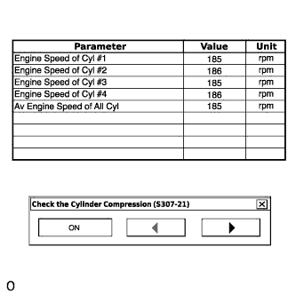
- HINT:
- At first, the Techstream displays extremely high cylinder engine speed values. After approximately 10 seconds of engine cranking, each cylinder engine speed measurement will change to the actual engine speed.
- NOTICE:
- Do not crank the engine continuously for 20 seconds or more.
- If it is necessary to crank the engine again after Check the Cylinder Compression has been changed to ON and the engine has been cranked once, press Exit to return to the Active Test menu screen. Then change Check the Cylinder Compression to ON and crank the engine.
- Use a fully-charged battery.
- Stop cranking the engine, and then change "Check the Cylinder Compression" to OFF after the engine stops.
- NOTICE:
- If the Active Test is changed to OFF while the engine is being cranked, the engine will start.
- Push the snapshot button to turn the snapshot function off.
- Select "Stored Data" on the Techstream screen, select the recorded data and display the data as a graph.
- HINT:
- If the data is not displayed as a graph, the change of the values cannot be observed.
- Check the change in engine speed values.
- HINT:
- As the data values of the Active Test return to their default values when cranking is stopped, the engine speed value of each cylinder cannot be observed. Therefore, it is necessary to use the data recorded with the snapshot function to check the engine speed values recorded during cranking.
| SYSTEM CHECK |
- HINT:
- Performing a System Check in the Utility menu enables the system, which consists of multiple actuators, to be operated without removing any parts. In addition, it can show whether or not any DTCs are set, and can detect potential malfunctions in the system.
Connect the Techstream to the DLC3.
Turn the ignition switch to ON.
Turn the Techstream on.
Enter the following menus: Powertrain / Engine and ECT / Utility / Evaporative System Check.
Perform the System Check by referring to the table below.
| Tester Display | Test Part | Control Range | Diagnostic Note |
| Evaporative System Check (Automatic Mode) | Perform 6 steps in order to operate EVAP key-off monitor automatically | 35°C (95°F) or less |
|
| Evaporative System Check (Manual Mode) | Perform 6 steps in order to operate EVAP key-off monitor manually | 35°C (95°F) or less |
|