Air Conditioning System (For Automatic Air Conditioning System) Generator Signal Circuit
DESCRIPTION
WIRING DIAGRAM
INSPECTION PROCEDURE
CHECK HARNESS AND CONNECTOR (A/C AMPLIFIER - GENERATOR)
INSPECT GENERATOR
AIR CONDITIONING SYSTEM (for Automatic Air Conditioning System) - Generator Signal Circuit |
DESCRIPTION
When the engine is started, the generator rotates and a pulsed voltage signal is generated. This signal is used by the A/C amplifier. The generated voltage signals sent from the generator are used for controlling the number of the heater elements to be heated.
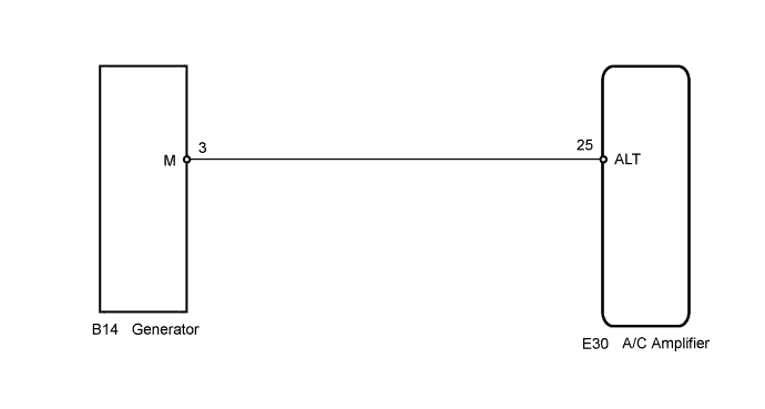
WIRING DIAGRAM
INSPECTION PROCEDURE
| 1.CHECK HARNESS AND CONNECTOR (A/C AMPLIFIER - GENERATOR) |
Disconnect the connector from the A/C amplifier.
Disconnect the connector from the generator.
Measure the resistance according to the value(s) in the table below.
- Standard Resistance:
Tester Connection
| Condition
| Specified Condition
|
E30-25 (ALT) - B14-3 (M)
| Always
| Below 1 Ω
|
E30-25 (ALT) - Body ground
| Always
| 10 kΩ or higher
|
| | REPAIR OR REPLACE HARNESS OR CONNECTOR |
|
|
Inspect the generator.
for 2AZ-FE:
Inspect the generator (COROLLA_ZRE142 RM000001AR909TX.html for On-vehicle Inspection, COROLLA_ZRE142 RM0000017VH02WX.html for Inspection).
for 2ZR-FE:
Inspect the generator (COROLLA_ZRE142 RM000001AR909SX.html for On-vehicle Inspection, COROLLA_ZRE142 RM000001ONN06UX.html for Inspection).
- Result:
Result
| Proceed to
|
OK
| A
|
NG (for 2AZ-FE)
| B
|
NG (for 2ZR-FE)
| C
|