Power Door Lock Control System Key Lock-In Prevention Function Does Not Work Properly
DESCRIPTION
WIRING DIAGRAM
INSPECTION PROCEDURE
READ VALUE USING TECHSTREAM (UNLOCK WARNING SWITCH AND COURTESY SWITCHES)
INSPECT UNLOCK WARNING SWITCH ASSEMBLY
CHECK HARNESS AND CONNECTOR (UNLOCK WARNING SWITCH - JUNCTION BLOCK)
CHECK HARNESS AND CONNECTOR (UNLOCK WARNING SWITCH - BODY GROUND)
INSPECT FRONT DOOR COURTESY LIGHT SWITCH ASSEMBLY (DRIVER SIDE)
CHECK HARNESS AND CONNECTOR (FRONT DOOR COURTESY LIGHT SWITCH - JUNCTION BLOCK)
INSPECT FRONT DOOR COURTESY LIGHT SWITCH ASSEMBLY (PASSENGER SIDE)
CHECK HARNESS AND CONNECTOR (FRONT DOOR COURTESY LIGHT SWITCH - JUNCTION BLOCK)
POWER DOOR LOCK CONTROL SYSTEM - Key Lock-in Prevention Function does not Work Properly |
DESCRIPTION
When the key is in the ignition key cylinder or the door courtesy switch ON signal is output to the main body ECU (instrument panel junction block), performing the door lock operation with the lock switch does not lock the door.
WIRING DIAGRAM
INSPECTION PROCEDURE
| 1.READ VALUE USING TECHSTREAM (UNLOCK WARNING SWITCH AND COURTESY SWITCHES) |
Connect the Techstream
Turn the ignition switch to ON.
Turn the Techstream on.
Enter the following menus: Body Electrical / Main Body / Data List.
Read the Data List according to the display on the Techstream.
Main BodyTester Display
| Measurement Item/Range
| Normal Condition
| Diagnostic Note
|
Key Unlock Warning SW
| Unlock warning switch signal / ON or OFF
| ON: Key is in ignition key cylinder
OFF: No key is in ignition key cylinder
| -
|
D Door Courtesy SW
| Driver side door courtesy light switch signal / ON or OFF
| ON: Driver side door is open
OFF: Driver side door is closed
| -
|
P Door Courtesy SW
| Passenger side door courtesy light switch signal / ON or OFF
| ON: Passenger side door is open
OFF: Passenger side door is closed
| -
|
- OK:
- The Techstream indicates ON or OFF according to the switch operation as shown in the table above.
- Result:
Result
| Proceed to
|
OK
| A
|
NG (Unlock Warning Switch)
| B
|
NG (Front Door Courtesy Light Switch (Driver Side))
| C
|
NG (Front Door Courtesy Light Switch (Passenger Side))
| D
|
| A |
|
|
|
| REPLACE MAIN BODY ECU (INSTRUMENT PANEL JUNCTION BLOCK) |
|
| 2.INSPECT UNLOCK WARNING SWITCH ASSEMBLY |
Remove the unlock warning switch (COROLLA_ZRE142 RM0000026TU02HX.html).
Measure the resistance according to the value(s) in the table below.
- Standard Resistance:
Tester Connection
| Switch Condition
| Specified Condition
|
1 (UN+) - 2 (UN-)
| Pushed
| 10 kΩ or higher
|
1 (UN+) - 2 (UN-)
| Not pushed
| Below 1 Ω
|
| 3.CHECK HARNESS AND CONNECTOR (UNLOCK WARNING SWITCH - JUNCTION BLOCK) |
Disconnect the 2E junction block connector.
Measure the resistance according to the value(s) in the table below.
- Standard Resistance:
Tester Connection
| Condition
| Specified Condition
|
E5-1 (UN+) - 2E-23 (KSW)
| Always
| Below 1 Ω
|
E5-1 (UN+) - Body ground
| Always
| 10 kΩ or higher
|
| | REPAIR OR REPLACE HARNESS OR CONNECTOR |
|
|
| 4.CHECK HARNESS AND CONNECTOR (UNLOCK WARNING SWITCH - BODY GROUND) |
Measure the resistance according to the value(s) in the table below.
- Standard Resistance:
Tester Connection
| Condition
| Specified Condition
|
E5-2 (UN-) - Body ground
| Always
| Below 1 Ω
|
| | REPAIR OR REPLACE HARNESS OR CONNECTOR |
|
|
| OK |
|
|
|
| REPLACE MAIN BODY ECU (INSTRUMENT PANEL JUNCTION BLOCK) |
|
| 5.INSPECT FRONT DOOR COURTESY LIGHT SWITCH ASSEMBLY (DRIVER SIDE) |
Remove the front door courtesy light switch (driver side) (COROLLA_ZRE142 RM000002VPS00OX.html).
Measure the resistance according to the value(s) in the table below.
- Standard Resistance:
Tester Connection
| Switch Condition
| Specified Condition
|
1 - Switch ground
| Not pushed (ON)
| Below 1 Ω
|
1 - Switch ground
| Pushed (OFF)
| 10 kΩ or higher
|
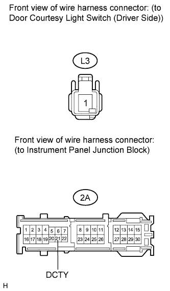
| 6.CHECK HARNESS AND CONNECTOR (FRONT DOOR COURTESY LIGHT SWITCH - JUNCTION BLOCK) |
Disconnect the 2A junction block connector.
Measure the resistance according to the value(s) in the table below.
- Standard Resistance:
Tester Connection
| Condition
| Specified Condition
|
L3-1 - 2A-21 (DCTY)
| Always
| Below 1 Ω
|
L3-1 - Body ground
| Always
| 10 kΩ or higher
|
| | REPAIR OR REPLACE HARNESS OR CONNECTOR |
|
|
| OK |
|
|
|
| REPLACE MAIN BODY ECU (INSTRUMENT PANEL JUNCTION BLOCK) |
|
| 7.INSPECT FRONT DOOR COURTESY LIGHT SWITCH ASSEMBLY (PASSENGER SIDE) |
Remove the front door courtesy light switch (passenger side) (COROLLA_ZRE142 RM0000017MQ020X.html).
Measure the resistance according to the value(s) in the table below.
- Standard Resistance:
Tester Connection
| Switch Condition
| Specified Condition
|
1 - Switch ground
| Not pushed (ON)
| Below 1 Ω
|
1 - Switch ground
| Pushed (OFF)
| 10 kΩ or higher
|
| 8.CHECK HARNESS AND CONNECTOR (FRONT DOOR COURTESY LIGHT SWITCH - JUNCTION BLOCK) |
Disconnect the 2E junction block connector.
Measure the resistance according to the value(s) in the table below.
- Standard Resistance:
Tester Connection
| Condition
| Specified Condition
|
M1-1 - 2E-20 (PCTY)
| Always
| Below 1 Ω
|
M1-1 - Body ground
| Always
| 10 kΩ or higher
|
| | REPAIR OR REPLACE HARNESS OR CONNECTOR |
|
|
| OK |
|
|
|
| REPLACE MAIN BODY ECU (INSTRUMENT PANEL JUNCTION BLOCK) |
|