Dtc B2276 Accr Signal Circuit Malfunction
DESCRIPTION
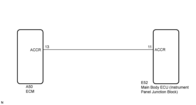
WIRING DIAGRAM
INSPECTION PROCEDURE
CHECK DTC OUTPUT
CHECK HARNESS AND CONNECTOR (MAIN BODY ECU (INSTRUMENT PANEL JUNCTION BLOCK) - ECM)
INSPECT MAIN BODY ECU (INSTRUMENT PANEL JUNCTION BLOCK)
DTC B2276 ACCR Signal Circuit Malfunction |
DESCRIPTION
The main body ECU (instrument panel junction block) will set this DTC if the ACCR signal sent from the ECM is ON for 40 seconds or more.- HINT:
- When the main body ECU (instrument panel junction block) is replaced with a new one and the cable from the negative (-) battery terminal is connected, the power source mode becomes the IG-ON mode. When the battery is removed and reinstalled, the power source mode that was selected when the battery was removed is restored.
- After the main body ECU (instrument panel junction block) is replaced, perform the registration procedures for the engine immobiliser system (COROLLA_ZRE142 RM000000QYF05AX.html).
DTC No.
| DTC Detection Condition
| Trouble Area
|
B2276
| ACCR output circuit inside main body ECU (instrument panel junction block) or other related circuit is malfunctioning
| - Main body ECU (instrument panel junction block)
- ECM
- Wire harness or connector
|
WIRING DIAGRAM
INSPECTION PROCEDURE
Clear the DTCs (COROLLA_ZRE142 RM000000YEH0CGX.html).
After all DTCs are cleared, check if the trouble occurs again 50 seconds after the engine switch is turned on (IG).
Check for DTCs again.
- OK:
- No DTC B2276 is output.
| 2.CHECK HARNESS AND CONNECTOR (MAIN BODY ECU (INSTRUMENT PANEL JUNCTION BLOCK) - ECM) |
Disconnect the E52 ECU connector.
Disconnect the A50 ECM connector.
Measure the resistance according to the value(s) in the table below.
- Standard Resistance:
Tester Connection
| Condition
| Specified Condition
|
E52-11 (ACCR) - A50-13 (ACCR)
| Always
| Below 1 Ω
|
E52-11 (ACCR) - Body ground
| Always
| 10 kΩ or higher
|
| | REPAIR OR REPLACE HARNESS OR CONNECTOR (MAIN BODY ECU (INSTRUMENT PANEL JUNCTION BLOCK) - ECM) |
|
|
| 3.INSPECT MAIN BODY ECU (INSTRUMENT PANEL JUNCTION BLOCK) |
Reconnect the E52 connector.
Measure the voltage according to the value(s) in the table below.
- Standard Voltage:
Tester Connection
| Condition
| Specified Condition
|
E52-11 (ACCR) - Body ground
| Brake pedal depressed, shift P, engine switch is pushed once → on (IG)
| 0.1 to 0.8 V*1 → output voltage at terminal AM1 or AM2 is -2 V or more.
|
- HINT:
- *1: Voltage is output only when the engine is cranking.
| OK |
|
|
|
| REPLACE MAIN BODY ECU (INSTRUMENT PANEL JUNCTION BLOCK) |
|