Front Drive Shaft Assembly (For 2Az-Fe) Installation
INSTALL FRONT DRIVE SHAFT HOLE SNAP RING LH (for LH Side)
INSTALL FRONT DRIVE SHAFT ASSEMBLY LH
INSTALL FRONT DRIVE SHAFT ASSEMBLY RH
INSTALL MANUAL TRANSMISSION CASE PROTECTOR (for Manual Transaxle)
INSTALL FRONT AXLE ASSEMBLY LH
INSTALL FRONT AXLE ASSEMBLY RH
CONNECT FRONT LOWER SUSPENSION ARM LH
CONNECT FRONT LOWER SUSPENSION ARM RH
INSTALL TIE ROD END SUB-ASSEMBLY LH
INSTALL TIE ROD END SUB-ASSEMBLY RH
INSTALL FRONT STABILIZER LINK ASSEMBLY LH
INSTALL FRONT STABILIZER LINK ASSEMBLY RH
CONNECT FRONT SPEED SENSOR LH (for TMC Made)
CONNECT FRONT SPEED SENSOR RH (for TMC Made)
CONNECT FRONT SPEED SENSOR LH (except TMC Made)
CONNECT FRONT SPEED SENSOR RH (except TMC Made)
INSTALL FRONT AXLE SHAFT NUT LH
INSTALL FRONT AXLE SHAFT NUT RH
INSTALL FRONT WHEELS
ADD MANUAL TRANSAXLE OIL (for Manual Transaxle)
ADD AUTOMATIC TRANSAXLE FLUID (for Automatic Transaxle)
INSPECT MANUAL TRANSAXLE OIL (for Manual Transaxle)
INSPECT AUTOMATIC TRANSAXLE FLUID (for Automatic Transaxle)
INSPECT FOR OIL LEAK (for Manual Transaxle)
INSPECT FOR FLUID LEAK (for Automatic Transaxle)
INSTALL ENGINE UNDER COVER LH
INSTALL ENGINE UNDER COVER RH
INSPECT AND ADJUST FRONT WHEEL ALIGNMENT
INSPECT SPEED SENSOR SIGNAL (w/o VSC)
INSPECT SPEED SENSOR SIGNAL (w/ VSC)
Front Drive Shaft Assembly (For 2Az-Fe) -- Installation |
| 1. INSTALL FRONT DRIVE SHAFT HOLE SNAP RING LH (for LH Side) |
Install a new front drive shaft hole snap ring LH to the front drive inboard joint assembly.
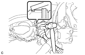
| 2. INSTALL FRONT DRIVE SHAFT ASSEMBLY LH |
Align the inboard joint splines, and using a brass bar and a hammer, install the front drive shaft assembly LH.
- NOTICE:
- Face the end gap of the front drive inboard joint hole snap ring downward.
- Do not damage the oil seal.
- Do not damage the inboard joint boot.
- HINT:
- Confirm whether the drive shaft is securely driven in by checking the reaction force and sound.
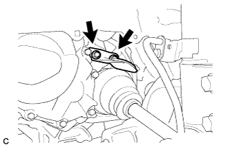
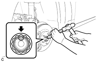
| 3. INSTALL FRONT DRIVE SHAFT ASSEMBLY RH |
Install the front drive shaft assembly RH.
Using a screwdriver, install a new bearing bracket hole snap ring.
- NOTICE:
- Do not damage the boot or oil seal.
- Move the drive shaft assembly while keeping it level.
Install a new bolt.
- Torque:
- 32 N*m{330 kgf*cm, 24 ft.*lbf}
| 4. INSTALL MANUAL TRANSMISSION CASE PROTECTOR (for Manual Transaxle) |
Install the manual transmission case protector with the 2 bolts.
- Torque:
- 18 N*m{184 kgf*cm, 13 ft.*lbf}
| 5. INSTALL FRONT AXLE ASSEMBLY LH |
Push the front axle assembly LH out of the vehicle to align the spline of the drive shaft with the front axle assembly LH and insert the front axle assembly LH.
- NOTICE:
- Do not push out the front axle further than necessary.
- Do not damage the outboard joint boot.
- Check for any foreign matter on the speed sensor rotor and insertion part.
- Do not damage the speed sensor rotor.
| 6. INSTALL FRONT AXLE ASSEMBLY RH |
- HINT:
- Perform the same procedure as for the LH side.
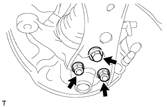
| 7. CONNECT FRONT LOWER SUSPENSION ARM LH |
Install the front lower suspension arm to the lower ball joint with the bolt and 2 nuts.
- Torque:
- 89 N*m{908 kgf*cm, 66 ft.*lbf}
| 8. CONNECT FRONT LOWER SUSPENSION ARM RH |
- HINT:
- Perform the same procedure as for the LH side.
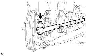
| 9. INSTALL TIE ROD END SUB-ASSEMBLY LH |
Connect the tie rod end sub-assembly LH to the steering knuckle with the nut.
- Torque:
- 49 N*m{500 kgf*cm, 36 ft.*lbf}
- NOTICE:
- Further tighten the nut up to 60° if the holes for the cotter pin are not aligned.
Install a new cotter pin.
| 10. INSTALL TIE ROD END SUB-ASSEMBLY RH |
- HINT:
- Perform the same procedure as for the LH side.
| 11. INSTALL FRONT STABILIZER LINK ASSEMBLY LH |
Install the front stabilizer link assembly to the front shock absorber with coil spring with the nut.
- Torque:
- 74 N*m{755 kgf*cm, 55 ft.*lbf}
- NOTICE:
- If the ball joint turns together with the nut, use a hexagon wrench (6 mm) to hold the stud bolt.
| 12. INSTALL FRONT STABILIZER LINK ASSEMBLY RH |
- HINT:
- Perform the same procedure as for the LH side.
| 13. CONNECT FRONT SPEED SENSOR LH (for TMC Made) |
Install the front speed sensor and front flexible hose to the front shock absorber with the bolt.
- Torque:
- 29 N*m{296 kgf*cm, 21 ft.*lbf}
- NOTICE:
- Do not twist the front speed sensor when installing it.
- HINT:
- Install the speed sensor harness bracket first, and then the front flexible hose.
| 14. CONNECT FRONT SPEED SENSOR RH (for TMC Made) |
- HINT:
- Perform the same procedure as for the LH side.
| 15. CONNECT FRONT SPEED SENSOR LH (except TMC Made) |
Install the front speed sensor and front flexible hose to the front shock absorber with the bolt.
- Torque:
- 29 N*m{296 kgf*cm, 21 ft.*lbf}
- NOTICE:
- Do not twist the front speed sensor when installing it.
- HINT:
- Install the speed sensor harness bracket first, and then the front flexible hose.
Install the front speed sensor with the clamp to the front shock absorber.
| 16. CONNECT FRONT SPEED SENSOR RH (except TMC Made) |
- HINT:
- Perform the same procedure as for the LH side.
| 17. INSTALL FRONT AXLE SHAFT NUT LH |
Clean the threaded parts on the drive shaft and axle shaft nut using a non-residue solvent.
- NOTICE:
- Be sure to perform this work for a new drive shaft.
- Keep the threaded parts free of oil and foreign matter.
Using a socket wrench (30 mm), install a new axle shaft nut.
- Torque:
- 216 N*m{2203 kgf*cm, 160 ft.*lbf}
Using a chisel and hammer, caulk the axle shaft nut.
| 18. INSTALL FRONT AXLE SHAFT NUT RH |
- HINT:
- Perform the same procedure as for the LH side.
- Torque:
- 103 N*m{1050 kgf*cm, 76 ft.*lbf}
| 20. ADD MANUAL TRANSAXLE OIL (for Manual Transaxle) |
Install a new gasket and the drain plug.
- Torque:
- 49 N*m{499 kgf*cm, 36 ft.*lbf}
Add manual transaxle oil.
Install the transmission filler plug and a new gasket.
- Torque:
- 49 N*m{499 kgf*cm, 36 ft.*lbf}
| 21. ADD AUTOMATIC TRANSAXLE FLUID (for Automatic Transaxle) |
| 22. INSPECT MANUAL TRANSAXLE OIL (for Manual Transaxle) |
Stop the vehicle in a level place.
Remove the transmission filler plug and the gasket.
Check that the oil surface is within 5 mm (0.197 in.) of the bottom of the transmission filler plug opening.
- NOTICE:
- Excessively large or small amounts of oil may cause problems.
- After replacing the oil, drive the vehicle and check the oil level again.
Check for oil leakage when the oil level is low.
Install the transmission filler plug and a new gasket.
- Torque:
- 49 N*m{499 kgf*cm, 36 ft.*lbf}
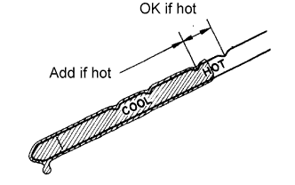
| 23. INSPECT AUTOMATIC TRANSAXLE FLUID (for Automatic Transaxle) |
- HINT:
- Drive the vehicle so that the engine and transaxle are at normal operating temperature.
- Fluid temperature:
- 70 to 80°C (158 to 176°F)
Park the vehicle on a level surface and set the parking brake.
With the engine idling and the brake pedal depressed, move the shift lever to all positions from P to S. Then return it to P.
Pull out the dipstick and wipe it clean.
Push the dipstick back fully into the pipe.
Pull the dipstick out again and check that the fluid level is within the HOT range. If the fluid level is below the HOT range, add new fluid and recheck the fluid level. If the fluid level exceeds the HOT range, drain the fluid once, add a proper amount of new fluid and recheck the fluid level.
| 24. INSPECT FOR OIL LEAK (for Manual Transaxle) |
| 25. INSPECT FOR FLUID LEAK (for Automatic Transaxle) |
| 26. INSTALL ENGINE UNDER COVER LH |
| 27. INSTALL ENGINE UNDER COVER RH |
| 28. INSPECT AND ADJUST FRONT WHEEL ALIGNMENT |
- HINT:
- (COROLLA_ZRE142 RM000001Y3B042X.html).
| 29. INSPECT SPEED SENSOR SIGNAL (w/o VSC) |
- HINT:
- (COROLLA_ZRE142 RM000001JBD052X.html).
| 30. INSPECT SPEED SENSOR SIGNAL (w/ VSC) |
- HINT:
- (COROLLA_ZRE142 RM000000XHT0ATX.html).