INSTALL DRIVE PLATE AND RING GEAR SUB-ASSEMBLY (for Automatic Transaxle)
INSTALL AUTOMATIC TRANSAXLE ASSEMBLY (for Automatic Transaxle)
TEMPORARILY TIGHTEN CENTER ENGINE MOUNTING MEMBER SUB-ASSEMBLY
INSTALL DRIVE PLATE AND TORQUE CONVERTER ASSEMBLY SETTING BOLT (for Automatic Transaxle)
INSTALL TRANSMISSION CONTROL CABLE ASSEMBLY (for Automatic Transaxle)
INSTALL TRANSMISSION CONTROL CABLE ASSEMBLY (for Manual Transaxle)
INSTALL CLUTCH RELEASE CYLINDER ASSEMBLY (for Manual Transaxle)
Engine Assembly -- Installation |
| 1. INSTALL ENGINE WIRE |
| 2. INSTALL DRIVE PLATE AND RING GEAR SUB-ASSEMBLY (for Automatic Transaxle) |
Clean the 8 bolts and 8 bolt holes.
Apply adhesive to 2 or 3 threads of the 8 bolts.
- Adhesive:
- Toyota Genuine Adhesive 1344, Three Bond 1344 or equivalent
 |
Using SST, hold the crankshaft.
- SST
- 09213-54015(91651-60855)
09330-00021
 |
Install the front drive plate spacer.
- HINT:
- Align the pin of the front spacer with the pin hole of the crankshaft.
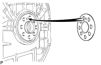 |
Install the drive plate and rear drive plate spacer onto the crankshaft.
 |
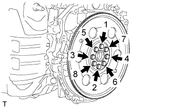
In several steps, uniformly install and tighten the 8 bolts in the sequence shown in the illustration.
- Torque:
- 98 N*m{999 kgf*cm, 72 ft.*lbf}
 |
| 3. INSTALL FLYWHEEL SUB-ASSEMBLY (for Manual Transaxle) |
Clean the 8 bolts and 8 bolt holes.
Apply adhesive to the end 2 or 3 threads of the 8 bolts.
- Adhesive:
- Toyota Genuine Adhesive 1344, Three Bond 1344 or equivalent
Using SST, hold the crankshaft.
- SST
- 09213-54015(91651-60855)
09330-00021
|
In several steps, uniformly install and tighten the 8 bolts in the sequence shown in the illustration.
- Torque:
- 130 N*m{1326 kgf*cm, 96 ft.*lbf}
 |
| 4. INSTALL CLUTCH DISC ASSEMBLY (for Manual Transaxle) |
- HINT:
| 5. INSTALL CLUTCH COVER ASSEMBLY (for Manual Transaxle) |
- HINT:
| 6. INSTALL AUTOMATIC TRANSAXLE ASSEMBLY (for Automatic Transaxle) |
- HINT:
- COROLLA_ZRE142 RM000000YWS032X_01_0003.html for U250E.
| 7. INSTALL MANUAL TRANSAXLE ASSEMBLY (for Manual Transaxle) |
- HINT:
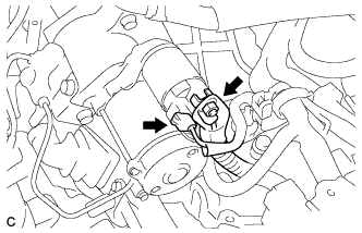
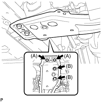
| 8. INSTALL STARTER ASSEMBLY (for Manual Transaxle) |
Install the starter assembly, clutch accumulator bracket and wire harness clamp bracket with the 3 bolts.
- Torque:
- Bolt A:
- 37 N*m{377 kgf*cm, 27 ft.*lbf}
- Bolt B:
- 12 N*m{120 kgf*cm, 9 ft.*lbf}
 |
Connect the wire harness to terminal 30 and install the nut. Then, attach the terminal cap.
- Torque:
- 9.8 N*m{100 kgf*cm, 87 in.*lbf}
 |
Connect the terminal 50 connector to the starter assembly.
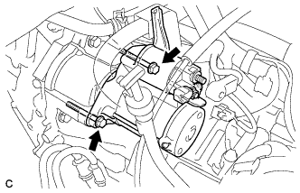
| 9. INSTALL STARTER ASSEMBLY (for Automatic Transaxle) |
Install the starter assembly and wire harness clamp bracket with the 2 bolts.
- Torque:
- 37 N*m{377 kgf*cm, 27 ft.*lbf}
 |
Connect the wire harness to terminal 30 and install the nut. Then, attach the terminal cap.
- Torque:
- 9.8 N*m{100 kgf*cm, 87 in.*lbf}
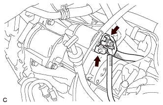 |
Connect the terminal 50 connector to the starter assembly.
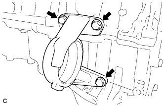
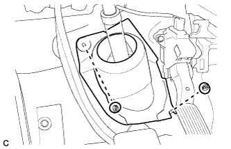
| 10. INSTALL DRIVE SHAFT BEARING BRACKET |
Install the drive shaft bearing bracket with the 3 bolts.
- Torque:
- 64 N*m{653 kgf*cm, 47 ft.*lbf}
 |
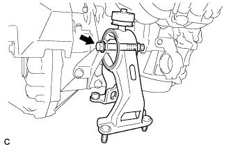
| 11. TEMPORARILY TIGHTEN FRONT ENGINE MOUNTING INSULATOR |
Temporarily install the front engine mounting insulator with the nut and through bolt.
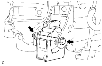 |
| 12. TEMPORARILY TIGHTEN REAR ENGINE MOUNTING INSULATOR |
Temporarily install the rear engine mounting insulator to the engine mounting bracket with the through bolt.
 |
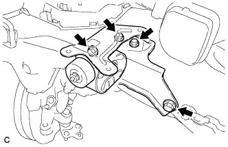
| 13. INSTALL ENGINE MOUNTING INSULATOR SUB-ASSEMBLY RH |
Install the engine mounting insulator RH with the 3 bolts.
- Torque:
- 52 N*m{530 kgf*cm, 38 ft.*lbf}
 |
| 14. INSTALL ENGINE MOUNTING INSULATOR LH |
Temporarily install the engine mounting insulator LH with the 4 bolts.
 |
Tighten the 4 bolts.
- Torque:
- 52 N*m{530 kgf*cm, 38 ft.*lbf}
- HINT:
- Perform this procedure only when replacement of the engine mounting insulator is necessary.
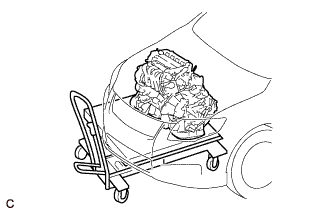
| 15. INSTALL ENGINE ASSEMBLY WITH TRANSAXLE |
Set the engine assembly with transaxle on the engine lifter.
- NOTICE:
- Place the engine on wooden blocks or equivalent so that the engine is level.
 |
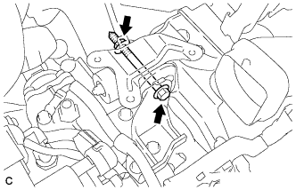
Remove the 2 bolts and 2 engine hangers.
Operate the engine lifter and lift the engine assembly with transaxle to the position where the engine mounting insulators RH and LH can be installed.
- CAUTION:
- Do not raise the engine more than necessary. If the engine is raised excessively, the vehicle may also be lifted up.
- NOTICE:
- Make sure that the engine is clear of all wiring and hoses.
- While raising the engine into the vehicle, do not allow it to contact the vehicle.
Install the engine mounting insulator RH with the bolt and 2 nuts.
- Torque:
- Nut A:
- 95 N*m{969 kgf*cm, 70 ft.*lbf}
- Nut B:
- 52 N*m{530 kgf*cm, 38 ft.*lbf}
- Bolt:
- 95 N*m{969 kgf*cm, 70 ft.*lbf}
 |
Install the engine mounting insulator LH with the through bolt and nut.
- Torque:
- 56 N*m{571 kgf*cm, 41 ft.*lbf}
 |
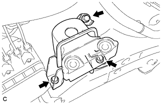
| 16. TEMPORARILY TIGHTEN CENTER ENGINE MOUNTING MEMBER SUB-ASSEMBLY |
Temporarily install the center engine mounting member sub-assembly with the 4 bolts.
 |
| 17. INSTALL FRONT SUSPENSION CROSSMEMBER SUB-ASSEMBLY |
While alternately inserting SST into the guide holes on both sides of the front suspension crossmember RH and LH, tighten 2 bolts (A), 2 bolts (B), 3 bolts (C), and 3 nuts (D) on the RH and LH sides to the respective specified torque in several steps.
- SST
- 09670-00010
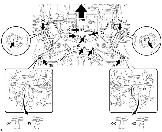
- Torque:
- Bolt A:
- 113 N*m{1152 kgf*cm, 83 ft.*lbf}
- Bolt B:
- 157 N*m{1600 kgf*cm, 116 ft.*lbf}
- Bolt C:
- 52 N*m{530 kgf*cm, 38 ft.*lbf}
- Nut D:
- 52 N*m{530 kgf*cm, 38 ft.*lbf}
| 18. FULLY TIGHTEN CENTER ENGINE MOUNTING MEMBER SUB-ASSEMBLY |
Fully tighten the center engine mounting member sub-assembly with the 4 bolts.
- Torque:
- Bolt A (TMC Made):
- 39 N*m{398 kgf*cm, 29 ft.*lbf}
- Bolt A (except TMC Made):
- 60 N*m{612 kgf*cm, 44 ft.*lbf}
- Bolt B (TMC Made):
- 52 N*m{530 kgf*cm, 38 ft.*lbf}
- Bolt B (except TMC Made):
- 81 N*m{826 kgf*cm, 60 ft.*lbf}
 |
| 19. FULLY TIGHTEN FRONT ENGINE MOUNTING INSULATOR |
Fully tighten the front engine mounting insulator with the nut and through bolt.
- Torque:
- 73 N*m{744 kgf*cm, 54 ft.*lbf}
|
| 20. FULLY TIGHTEN REAR ENGINE MOUNTING INSULATOR |
Fully tighten the rear engine mounting insulator to the engine mounting bracket with the through bolt.
- Torque:
- 65 N*m{663 kgf*cm, 48 ft.*lbf}
|
| 21. INSTALL DRIVE PLATE AND TORQUE CONVERTER ASSEMBLY SETTING BOLT (for Automatic Transaxle) |
- HINT:
- COROLLA_ZRE142 RM000000YWS032X_01_0028.html for U250E.
| 22. INSTALL FRONT DRIVE SHAFT HOLE SNAP RING LH |
Install a new front drive shaft hole snap ring LH to the front drive inboard joint assembly.
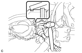
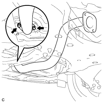
| 23. INSTALL FRONT DRIVE SHAFT ASSEMBLY LH |
Align the inboard joint splines, and using a brass bar and a hammer, install the front drive shaft assembly LH.
- NOTICE:
- Face the end gap of the front drive inboard joint hole snap ring downward.
- Do not damage the oil seal.
- Do not damage the inboard joint boot.
- HINT:
- Confirm whether the drive shaft is securely driven in by checking the reaction force and sound.
 |
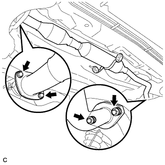
| 24. INSTALL FRONT DRIVE SHAFT ASSEMBLY RH |
Install the front drive shaft assembly RH.
 |
Using a screwdriver, install a new bearing bracket hole snap ring.
- NOTICE:
- Do not damage the boot or oil seal.
- Move the drive shaft assembly while keeping it level.
Install a new bolt.
- Torque:
- 32 N*m{330 kgf*cm, 24 ft.*lbf}
| 25. INSTALL STEERING KNUCKLE WITH AXLE HUB LH |
Align the matchmarks and connect the front drive shaft assembly to the front axle assembly LH.
 |
| 26. INSTALL STEERING KNUCKLE WITH AXLE HUB RH |
- HINT:
- Perform the same procedure for the LH side.
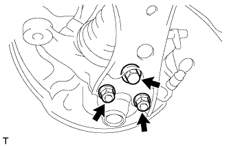
| 27. CONNECT FRONT LOWER SUSPENSION ARM LH |
Install the front lower suspension arm to the lower ball joint with the bolt and 2 nuts.
- Torque:
- 89 N*m{908 kgf*cm, 66 ft.*lbf}
 |
| 28. CONNECT FRONT LOWER SUSPENSION ARM RH |
- HINT:
- Perform the same procedure for the LH side.
| 29. INSTALL FRONT STABILIZER LINK ASSEMBLY LH |
Install the front stabilizer link assembly to the front shock absorber with coil spring with the nut.
- Torque:
- 74 N*m{755 kgf*cm, 55 ft.*lbf}
- NOTICE:
- If the ball joint turns together with the nut, use a hexagon wrench (6 mm) to hold the stud bolt.
 |
| 30. INSTALL FRONT STABILIZER LINK ASSEMBLY RH |
- HINT:
- Perform the same procedure for the LH side.
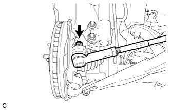
| 31. INSTALL TIE ROD END SUB-ASSEMBLY LH |
Connect the tie rod end sub-assembly LH to the steering knuckle with the nut.
- Torque:
- 49 N*m{500 kgf*cm, 36 ft.*lbf}
- NOTICE:
- Further tighten the nut up to 60° if the holes for the cotter pin are not aligned.
 |
Install a new cotter pin.
| 32. INSTALL TIE ROD END SUB-ASSEMBLY RH |
- HINT:
- Perform the same procedure for the LH side.
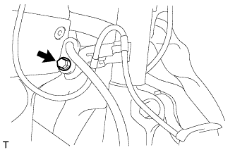
| 33. INSTALL FRONT SPEED SENSOR LH |
Install the front flexible hose and front speed sensor with the bolt.
- Torque:
- 29 N*m{296 kgf*cm, 21 ft.*lbf}
- NOTICE:
- Install the flexible hose and speed sensor without twisting them.
 |
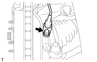
Install the front speed sensor onto the steering knuckle with the bolt.
- Torque:
- 8.5 N*m{87 kgf*cm, 75 in.*lbf}
 |
| 34. INSTALL FRONT SPEED SENSOR RH |
- HINT:
- Perform the same procedure for the LH side.
| 35. INSTALL FRONT AXLE SHAFT NUT LH |
Clean the threaded parts on the drive shaft and axle shaft nut using a non-residue solvent.
- NOTICE:
- Be sure to perform this work for a new drive shaft.
- Keep the threaded parts free of oil and foreign matter.
Using a socket wrench (30 mm), install a new axle shaft nut.
- Torque:
- 216 N*m{2203 kgf*cm, 160 ft.*lbf}
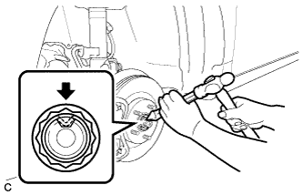 |
Using a chisel and hammer, caulk the axle shaft nut.
| 36. INSTALL FRONT AXLE SHAFT NUT RH |
- HINT:
- Perform the same procedure for the LH side.
| 37. INSTALL FRONT EXHAUST PIPE ASSEMBLY |
Using a vernier caliper, measure the free length of the compression springs.
Minimum 41.5 mm (1.63 in.) - HINT:
- If the free length is less than the minimum, replace the compression spring.
 |
Remove the remains of exhaust manifold converter with wire brash.
Fully insert a new gasket to the exhaust manifold.
- NOTICE:
- Be sure to install the gasket in the correct direction.
- Do not reuse the gasket.
- Do not damage the gasket.
 |
Install the front exhaust pipe assembly with the 2 bolts and 2 compression springs.
- Torque:
- 43 N*m{440 kgf*cm, 32 ft.*lbf}
 |
Connect the heated oxygen sensor connector.
| 38. INSTALL CENTER EXHAUST PIPE ASSEMBLY |
Using a vernier caliper, measure the free length of the compression springs.
Minimum 38.5 mm (1.52 in.) - HINT:
- If the free length is less than the minimum, replace the compression spring.
|
Fully insert a new gasket to the center exhaust pipe assembly.
- NOTICE:
- Be sure to install the gasket in the correct direction.
- Do not reuse the gasket.
- Do not damage the gasket.
 |
Install a new gasket to the front exhaust pipe assembly.
Connect the center exhaust pipe assembly to the 2 exhaust pipe supports.
Install the center exhaust pipe assembly with the 4 bolts and 2 compression springs.
- Torque:
- 43 N*m{440 kgf*cm, 32 ft.*lbf}
 |
| 39. INSTALL NO. 1 STEERING COLUMN HOLE COVER SUB-ASSEMBLY |
 |
Engage clip B onto the body and install the No. 1 steering column hole cover sub-assembly onto the body with clips A.
- NOTICE:
- Make sure that the lip of the No. 1 steering column hole cover sub-assembly is not damaged.
| 40. INSTALL NO. 2 STEERING INTERMEDIATE SHAFT ASSEMBLY |
Align the matchmarks on the No. 2 steering intermediate shaft assembly and the steering intermediate shaft assembly.
 |
Install the bolt.
- Torque:
- 35 N*m{360 kgf*cm, 26 ft.*lbf}
| 41. INSTALL COLUMN HOLE COVER SILENCER SHEET |
Install the column hole cover silencer sheet with the 2 clips.
 |
Install the floor carpet.
| 42. INSTALL TRANSMISSION CONTROL CABLE ASSEMBLY (for Automatic Transaxle) |
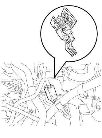
Connect the transmission control cable to the control cable bracket.
 |
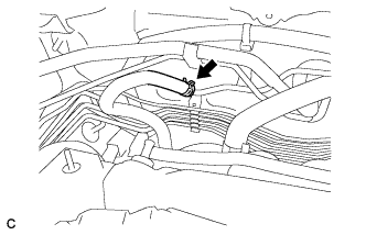
Connect the transmission control cable to the bracket with a new clip.
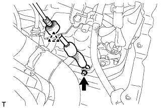 |
Connect the transmission control cable assembly to the control shaft lever with the nut.
- Torque:
- 12 N*m{122 kgf*cm, 9 ft.*lbf}
| 43. INSTALL TRANSMISSION CONTROL CABLE ASSEMBLY (for Manual Transaxle) |
Install the 2 transmission control cables to the control cable bracket with 2 new clips*1.
 |
Install the 2 transmission control cables to the transaxle with 2 new clips*2.
| 44. INSTALL CLUTCH RELEASE CYLINDER ASSEMBLY (for Manual Transaxle) |
- HINT:
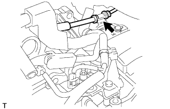
| 45. CONNECT UNION TO CONNECTOR TUBE HOSE |
Connect the union to connector tube hose.
 |
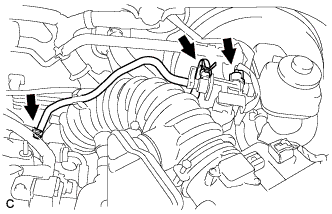
| 46. INSTALL FUEL TUBE SUB-ASSEMBLY |
Connect the fuel tube connector and fuel pipe.
- CAUTION:
- Align the fuel tube connector with the pipe, then push the fuel tube connector in until the retainer makes a "click" sound. If the connection is tight, apply a small amount of engine oil to the tip of the pipe. After connecting, pull the pipe and connector to make sure that they are securely connected.
Engage the claw and install the No. 1 fuel pipe clamp.
 |
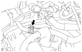
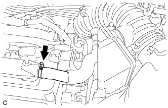
| 47. CONNECT INLET HEATER WATER HOSE |
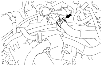
Connect the inlet heater water hose with the clamp.
 |
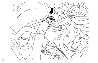
| 48. CONNECT OUTLET HEATER WATER HOSE |
Connect the outlet heater water hose with the clamp.
 |
| 49. INSTALL BREATHER HOSE (for Automatic Transaxle) |
Install the breather hose.
 |
| 50. CONNECT OIL COOLER HOSE (for Automatic Transaxle) |
Connect the 2 oil cooler hoses with the clamps.
 |
| 51. INSTALL NO. 1 RADIATOR HOSE |
Connect the No. 1 radiator hose with the clamp.
 |
| 52. INSTALL NO. 2 RADIATOR HOSE |
Connect the No. 2 radiator hose with the clamp.
 |
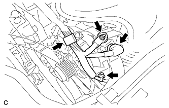
| 53. INSTALL COMPRESSOR ASSEMBLY WITH PULLEY |
Using a "TORX" socket wrench (E8), install the compressor assembly with pulley with the 2 stud bolts.
- Torque:
- 9.8 N*m{100 kgf*cm, 87 in.*lbf}
 |
Install the compressor assembly with pulley with the 2 bolts and the 2 nuts.
- HINT:
- Tighten the bolts and the nuts in the order shown in the illustration.
- Torque:
- 25 N*m{255 kgf*cm, 18 ft.*lbf}
 |
Connect the connector.
| 54. INSTALL GENERATOR ASSEMBLY |
Install the wire harness clamp bracket with the bolt.
 |
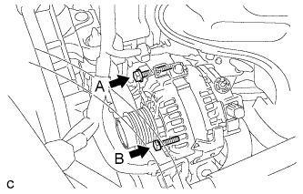
Install the generator assembly with the 2 bolts.
- Torque:
- Bolt A:
- 52 N*m{530 kgf*cm, 38 ft.*lbf}
- Bolt B:
- 21 N*m{215 kgf*cm, 16 ft.*lbf}
 |
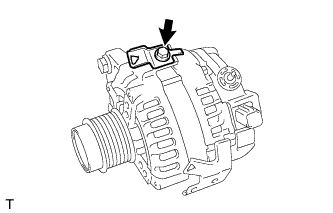
Install the wire harness to terminal B with the nut.
- Torque:
- 9.8 N*m{100 kgf*cm, 87 in.*lbf}
 |
Attach the clamp and connect the generator connector to the generator.
Install the 2 wire harness clamps.
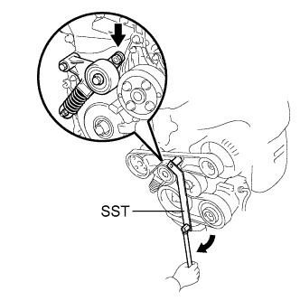
| 55. INSTALL V-RIBBED BELT |
 |
- HINT:
- The illustration shows the V-ribbed belt layout.
Using SST, slowly turn the V-ribbed belt tensioner clockwise and install the V-ribbed belt.
- SST
- 09216-42010(09216-04010)
- NOTICE:
- Make sure that SST and other tools are set to the tensioner securely.
- When compressing the V-ribbed belt tensioner, slowly turn the tensioner.
 |
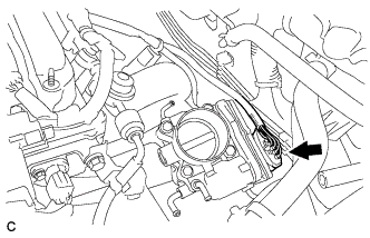
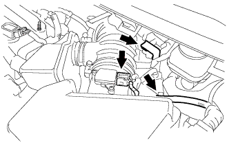
| 56. INSTALL THROTTLE BODY ASSEMBLY |
Install a new gasket onto the intake manifold.
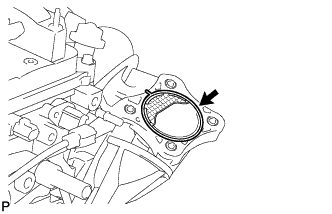 |
Install the throttle body assembly with the 4 bolts.
- Torque:
- 30 N*m{306 kgf*cm, 22 ft.*lbf}
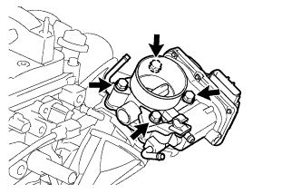 |
Connect the throttle body connector.
 |
Connect the 2 water by-pass hoses.
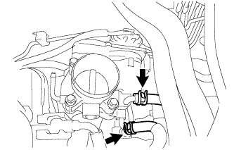 |
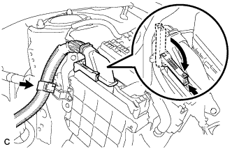
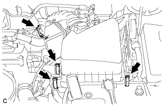
| 57. INSTALL WIRE HARNESS |
Install the ground cable to the transmission with the bolt and clamp (for Manual Transaxle).
- Torque:
- 13 N*m{130 kgf*cm, 10 ft.*lbf}
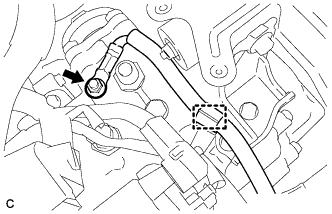 |
Install the earth wire to the transmission with the bolt and clamp (for Automatic Transaxle).
- Torque:
- 26 N*m{260 kgf*cm, 19 ft.*lbf}
 |
Install the wire harness with the 2 nuts.
- Torque:
- 8.4 N*m{85 kgf*cm, 74 in.*lbf}
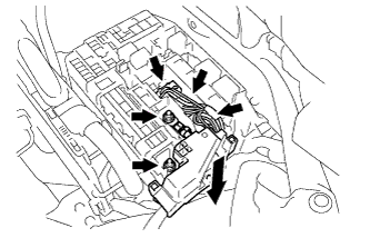 |
Connect the 3 connectors
Connect the connector to the ECM with the clamp and lock lever.
 |
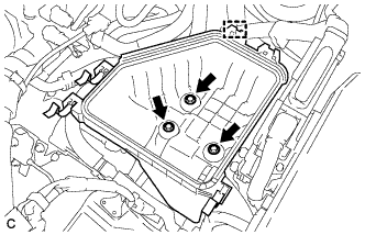
| 58. INSTALL BATTERY CARRIER |
Install the battery carrier with the 4 bolts.
- Torque:
- 13 N*m{133 kgf*cm, 10 ft.*lbf}
 |
Connect the 2 wire harness clamps.
| 59. INSTALL BATTERY |
Install the battery tray, battery and battery insulator.
Install the battery clamp with the bolt and nut.
- Torque:
- Bolt:
- 6.5 N*m{66 kgf*cm, 58 in.*lbf}
- Nut:
- 3.5 N*m{36 kgf*cm, 31 in.*lbf}
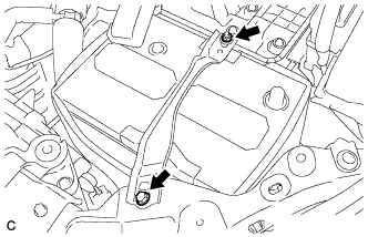 |
Connect the battery cables.
- Torque:
- 5.4 N*m{55 kgf*cm, 48 in.*lbf}
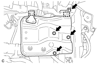
| 60. INSTALL AIR CLEANER CASE |
Install the air cleaner case with the 3 bolts.
- Torque:
- 7.0 N*m{71 kgf*cm, 62 in.*lbf}
 |
Install the engine wire clamp to the air cleaner case.
Install the air cleaner filter element.
| 61. INSTALL AIR CLEANER CAP SUB-ASSEMBLY WITH HOSE |
Install the air cleaner cap sub-assembly with hose and lock the 3 clamps.
 |
Tighten the air cleaner hose clamp.
Connect the ventilation hose.
 |
Connect the 2 vacuum hoses and No. 1 vacuum switching valve connector.
 |
Connect the 2 wire harness clamps and the mass air flow meter connector.
 |
| 62. INSTALL RADIATOR RESERVE TANK ASSEMBLY |
Install the radiator reserve tank assembly with the 3 bolts.
- Torque:
- 7.0 N*m{71 kgf*cm, 62 in.*lbf}
 |
| 63. ADD MANUAL TRANSAXLE OIL (for Manual Transaxle) |
- HINT:
| 64. INSPECT MANUAL TRANSAXLE OIL (for Manual Transaxle) |
- HINT:
| 65. ADD AUTOMATIC TRANSAXLE FLUID (for Automatic Transaxle) |
- HINT:
- COROLLA_ZRE142 RM000000YWW02NX_01_0015.html for U250E.
| 66. INSPECT AUTOMATIC TRANSAXLE FLUID (for Automatic Transaxle) |
- HINT:
- COROLLA_ZRE142 RM000000YWW02NX_01_0021.html for U250E.
| 67. INSPECT SHIFT LEVER POSITION (for Automatic Transaxle) |
- HINT:
- COROLLA_ZRE142 RM0000020U504OX_01_0021.html for U250E.
| 68. ADJUST SHIFT LEVER POSITION (for Automatic Transaxle) |
- HINT:
- COROLLA_ZRE142 RM0000020U504OX_01_0022.html for U250E.
| 69. ADD ENGINE COOLANT |
Tighten the lower radiator drain cock plug.
Tighten the cylinder block drain cock plug.
- Torque:
- 13 N*m{130 kgf*cm, 9 ft.*lbf}
Loosen the upper radiator drain cock plug.
Slowly fill the radiator with TOYOTA Super Long Life Coolant (SLLC).
- Standard Capacity:
Item Capacity Engine coolant 5.7 liters (6.0 US qts, 5.0 lmp. qts)
- HINT:
- TOYOTA vehicles are filled with TOYOTA SLLC at the factory. In order to avoid damage to the engine cooling system and other technical problems, only use TOYOTA SLLC or similar high quality ethylene glycol based non-silicate, non-amine, non-nitrite, non-borate coolant with long-life hybrid organic acid technology (coolant with long-life hybrid organic acid technology consists of a combination of low phosphates and organic acids).
- Contact your TOYOTA dealer for further details.
- NOTICE:
- Never use water as a substitute for engine coolant.
Squeeze the inlet and outlet radiator hoses several times by hand, and then check the level of the coolant.
If the coolant level is low, add coolant.
Tighten the upper radiator drain cock plug.
Slowly pour coolant into the radiator reservoir tank until it reaches the FULL line.
Install the radiator cap sub-assembly and reservoir tank cap.
Start the engine and warm it up.
Bleed air from the cooling system.
- NOTICE:
- Before starting the engine, turn the A/C switch off.
- Adjust the air conditioning temperature setting to MAX (HOT).
- Adjust the air conditioning blower setting to LO.
Warm up the engine until the thermostat opens. While the thermostat is open, allow the coolant to circulate for several minutes.
- HINT:
- Thermostat opening timing can be determined by squeezing the inlet radiator hose, and sensing vibrations when the engine coolant starts to flow inside the hose.
- CAUTION:
- When squeezing the radiator hoses:
- Wear protective gloves.
- Be careful as the radiator hoses are hot.
- Keep your hands away from the radiator fan.
Stop the engine, and wait until the engine coolant cools down.
Add engine coolant to the FULL line on the radiator reservoir.
| 70. WARM UP ENGINE |
| 71. FILL BRAKE FLUID RESERVOIR (for Manual Transaxle) |
- HINT:
| 72. BLEED CLUTCH LINE (for Manual Transaxle) |
- HINT:
| 73. INSPECT FLUID LEVEL (for Manual Transaxle) |
- HINT:
| 74. INSPECT FOR FUEL LEAK |
Check fuel pump operation.
Connect the Techstream to the DLC3.
Turn the ignition switch to ON and turn the Techstream on.
- NOTICE:
- Do not start the engine.
Enter the following menus: Powertrain / Engine and ECT / Active Test / Control the Fuel Pump / Speed.
Check for pressure in the fuel inlet tube from the fuel line. Check that sounds of fuel flowing from the fuel tank can be heard. If no sounds can be heard, check the integration relay, fuel pump, ECM and wiring connectors.
Check for fuel leaks.
There is no fuel leakage after performing maintenance anywhere on the fuel system. If there is a fuel leak, repair or replace parts as necessary.
Turn the ignition switch off.
Disconnect the Techstream from the DLC3.
| 75. INSPECT FOR COOLANT LEAK |
 |
- CAUTION:
- To avoid the danger of being burned, do not remove the radiator cap sub-assembly while the engine and radiator assembly are still hot. Thermal expansion will cause hot engine coolant and steam to blow out from the radiator assembly.
Fill the radiator assembly with engine coolant, then attach a radiator cap tester.
Pump the tester to 118 kPa (1.2 kgf/cm2, 17.1 psi), then check that the pressure does not drop.
If the pressure drops, check the hoses, radiator assembly and water pump assembly for leakage. If there are no signs or traces of external engine coolant leakage, check the heater core, cylinder block and head.
| 76. INSPECT FOR OIL LEAK |
| 77. INSPECT FOR EXHAUST GAS LEAK |
| 78. INSTALL ENGINE UNDER COVER LH |
| 79. INSTALL ENGINE UNDER COVER RH |
| 80. INSTALL FRONT WHEELS |
- Torque:
- 103 N*m{1050 kgf*cm, 76 ft.*lbf}
| 81. INSPECT IGNITION TIMING |
- NOTICE:
- Turn all the electrical systems and the A/C off.
- When checking the ignition timing, move the shift lever to neutral.
Warm up and stop the engine.
When using the Techstream:
Connect the Techstream to the DLC3.
Turn the ignition switch to ON.
Turn the Techstream on.
Enter the following menus: Power Train / Engine and ECT / Data List / IGN Advance
Start the engine.
According to the display on the Techstream, read the Data List.
- Standard ignition timing:
- 5 to 15° BTDC at idle
Check that the ignition timing advances immediately when the engine speed is increased.
Turn the ignition switch off.
Disconnect the Techstream from the DLC3.
When not using the Techstream:
Remove the No. 1 engine cover sub-assembly (COROLLA_ZRE142 RM000001BC301CX_01_0101.html).
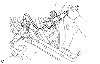
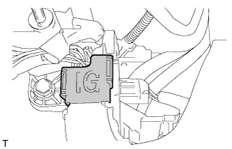
Open the ignition cover located to the right of the No. 4 ignition coil.
Pull the wire harness out from the IG cover.
Connect the timing light to the wire harness.
- NOTICE:
- Use a timing light that detects the primary signal.
Using SST, connect terminals 13 (TC) and 4 (CG) of the DLC3.
- SST
- 09843-18040
Allow the engine to idle and check the ignition timing.
- Standard ignition timing:
- 8 to 12° BTDC at idle
- HINT:
- Run the engine at 1000 to 1300 rpm for 5 seconds, then check that the engine speed returns to idle speed.
Disconnect SST from terminals 13 (TC) and 4 (CG) of the DLC3.
Allow the engine to idle and check the ignition timing.
- Standard ignition timing:
- 5 to 15° BTDC at idle
Check that the ignition timing advances immediately when the engine speed is increased.
Turn the ignition switch off.
Remove the timing light.
Close the IG cover.
Install the No. 1 engine cover sub-assembly (COROLLA_ZRE142 RM000001BC101CX_01_0268.html).

| 82. INSPECT ENGINE IDLING SPEED |
- NOTICE:
- Turn all the electrical systems and the A/C off.
- When checking the idle speed, move the shift lever to P or neutral.
Warm up and stop the engine.
When using the Techstream:
Connect the Techstream to the DLC3.
Turn the ignition switch to ON.
Turn the Techstream on.
Enter the following menus: Power Train / Engine and ECT / Data List / Engine Speed
Start the engine.
According to the display on the Techstream, read the Data List.
- Standard idle speed:
- 600 to 700 rpm
Turn the ignition switch off.
Disconnect the Techstream from the DLC3.
When not using the Techstream:
Turn off all the accessories and air conditioning.
Move the shift lever to P or neutral.
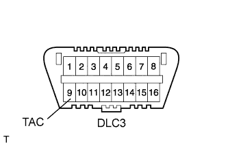
Connect SST to 9 (TAC) of the DLC3 terminal, and then connect a tachometer to SST.
- SST
- 09843-18030
Start the engine.
Check the idle speed with the cooling fan off.
- Standard idle speed:
- 600 to 700 rpm
Turn the ignition switch off.
Remove the tachometer and disconnect SST from the DLC3.
| 83. INSPECT CO/HC |
- HINT:
- This check determines whether or not the idle CO/HC complies with local regulations.
Start and warm up the engine.
Run the engine at 2500 rpm for approximately 180 seconds.
Insert the CO/HC meter testing probe at least 40 cm (1.3 ft.) into the tailpipe while idling.
Inspect the CO/HC concentration during idle at 2500 rpm.
If the CO/HC concentration does not comply with local regulations, troubleshoot in the order given below.Check the A/F sensor and heated oxygen sensor operation.
See the table below for possible causes, then inspect the applicable parts and repair them if necessary.
CO HC Problem Possible Cause Normal High Rough idle 1. Faulty ignition:
- Incorrect timing
- Plugs are contaminated, shorted, or gaps are defective
2. Incorrect valve clearance
3. Leaks in intake and exhaust valve
4. Leaks in cylindersLow High Rough idle
(Fluctuating HC reading)1. Vacuum leakage:
- Ventilation hoses
- Intake manifold
- Throttle body
- Brake booster line
2. Lean mixture causing misfireHigh High Rough idle
(Black smoke from exhaust)1. Restricted air filter
2. Plugged PCV valve
3. Faulty EFI system:
- Faulty pressure regulator
- Faulty engine coolant temperature sensor
- Faulty mass air flow meter
- Faulty ECM
- Faulty injectors
- Faulty throttle body
| 84. ADJUST FRONT WHEEL ALIGNMENT |
- HINT:
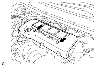
| 85. INSTALL NO. 1 ENGINE COVER SUB-ASSEMBLY |
Install the No. 1 engine cover sub-assembly with the 2 nuts.
 |
| 86. CHECK ABS SPEED SENSOR SIGNAL |
- HINT:
- COROLLA_ZRE142 RM000001JBD052X.html for ABS.
- COROLLA_ZRE142 RM000000XHT0ATX.html for VSC.