Audio And Visual System (W/ Multi-Display Without Dvd Player) Steering Pad Switch Circuit
DESCRIPTION
WIRING DIAGRAM
INSPECTION PROCEDURE
CHECK HARNESS AND CONNECTOR (STEERING PAD SWITCH SIGNAL)
INSPECT STEERING PAD SWITCH
INSPECT SPIRAL CABLE SUB-ASSEMBLY
AUDIO AND VISUAL SYSTEM (w/ Multi-display without DVD Player) - Steering Pad Switch Circuit |
DESCRIPTION
This circuit sends an operation signal from the steering pad switch assembly*1 or steering pad switch LH*2 to the radio and display receiver assembly.If there is an open in the circuit, the audio system cannot be operated using the steering pad switch assembly*1 or steering pad switch LH*2.If there is a short in the circuit, the same condition as when a switch is continuously depressed occurs.Therefore, the radio and display receiver assembly cannot be operated using the steering pad switch assembly*1 or steering pad switch LH*2, and also the radio and display receiver assembly itself cannot function.- *1: w/ Steering Pad Switch Assembly
- *2: w/ Steering Pad Switch LH
WIRING DIAGRAM
INSPECTION PROCEDURE
- NOTICE:
- The vehicle is equipped with a Supplemental Restraint System (SRS) which includes components such as airbags. Before servicing (including removal or installation of parts), be sure to read the precaution for Supplemental Restraint System (COROLLA_ZRE142 RM000000KT10H0X.html).
| 1.CHECK HARNESS AND CONNECTOR (STEERING PAD SWITCH SIGNAL) |
Disconnect the E129 radio and display receiver assembly connector.
Measure the resistance according to the value(s) in the table below.
- Standard Resistance:
Tester Connection
| Condition
| Specified Condition
|
E129-21 (SW1) - E129-23 (SWG)
| No switch pushed
| 95 to 105 kΩ
|
Seek+ switch pushed
| Below 2.5 Ω
|
Seek- switch pushed
| 313 to 345 Ω
|
Volume+ switch pushed
| 950 to 1050 Ω
|
Volume- switch pushed
| 2955 to 3265 Ω
|
E129-22 (SW2) - E129-23 (SWG)
| No switch pushed
| 95 to 105 kΩ
|
MODE switch pushed
| Below 2.5 Ω
|
On hook switch pushed*1
| 313 to 345 Ω
|
Off hook switch pushed*1
| 950 to 1050 Ω
|
Voice switch pushed*1
| 2955 to 3265 Ω
|
- *1: w/ Steering Pad Switch Assembly
| 2.INSPECT STEERING PAD SWITCH |
Disconnect the Y1 steering pad switch assembly*1 or steering pad switch LH*2 connector (for Type A).
- *1: w/ Steering Pad Switch Assembly
- *2: w/ Steering Pad Switch LH
Disconnect the Y1 steering pad switch assembly*1 or steering pad switch LH*2 connector (for Type B).
- *1: w/ Steering Pad Switch Assembly
- *2: w/ Steering Pad Switch LH
Measure the resistance according to the value(s) in the table below.
- Standard Resistance:
Tester Connection
| Condition
| Specified Condition
|
Y1-10 (AU1) - Y1-8 (EAU)
| No switch pushed
| 95 to 105 kΩ
|
Seek+ switch pushed
| Below 2.5 Ω
|
Seek- switch pushed
| 313 to 345 Ω
|
Volume+ switch pushed
| 950 to 1050 Ω
|
Volume- switch pushed
| 2955 to 3265 Ω
|
Y1-9 (AU2) - Y1-8 (EAU)
| No switch pushed
| 95 to 105 kΩ
|
MODE switch pushed
| Below 2.5 Ω
|
On hook switch pushed*1
| 313 to 345 Ω
|
Off hook switch pushed*1
| 950 to 1050 Ω
|
Voice switch pushed*1
| 2955 to 3265 Ω
|
- *1: w/ Steering Pad Switch Assembly
Text in Illustration*A
| for Type A
| *B
| for Type B
|
*C
| w/ Steering Pad Switch Assembly
| -
| -
|
*a
| Component without harness connected
(Steering Pad Switch)
| *b
| Volume+
|
*c
| Volume-
| *d
| Seek+
|
*e
| Seek-
| *f
| MODE
|
*g
| On hook
| *h
| Off hook
|
*i
| Voice
| -
| -
|
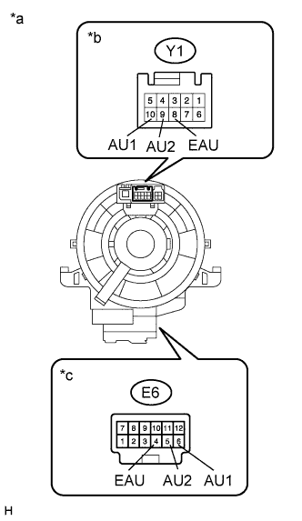
| 3.INSPECT SPIRAL CABLE SUB-ASSEMBLY |
Disconnect the Y1 steering pad switch assembly*1 or steering pad switch LH*2 connector.
- *1: w/ Steering Pad Switch Assembly
- *2: w/ Steering Pad Switch LH
Disconnect the E6 spiral cable sub-assembly connector.
Measure the resistance according to the value(s) in the table below.
- Standard Resistance:
Tester Connection
| Condition
| Specified Condition
|
Y1-8 (EAU) - E6-4 (EAU)
| Center
| Below 1 Ω
|
2.5 rotations to the left
|
2.5 rotations to the right
|
Y1-10 (AU1) - E6-6 (AU1)
| Center
| Below 1 Ω
|
2.5 rotations to the left
|
2.5 rotations to the right
|
Y1-9 (AU2) - E6-5 (AU2)
| Center
| Below 1 Ω
|
2.5 rotations to the left
|
2.5 rotations to the right
|
After setting the spiral cable sub-assembly to the center position, rotate the spiral cable sub-assembly 2.5 times clockwise. Then while rotating the spiral cable sub-assembly 5 times counterclockwise, measure the resistance as shown in the table below.
- Standard Resistance:
Tester Connection
| Condition
| Specified Condition
|
Y1-8 (EAU) - E6-4 (EAU)
| Always
| Below 1 Ω
|
Y1-10 (AU1) - E6-6 (AU1)
| Always
| Below 1 Ω
|
Y1-9 (AU2) - E6-5 (AU2)
| Always
| Below 1 Ω
|
- NOTICE:
- The spiral cable sub-assembly is an important part of the SRS airbag system. Incorrect removal or installation of the spiral cable sub-assembly may prevent the airbag from deploying. Refer to the pages shown in the brackets.
- As the spiral cable sub-assembly may break, do not rotate the spiral cable sub-assembly more than the specified amount.
- HINT:
- Removal (COROLLA_ZRE142 RM000000UWD09PX.html)
Text in Illustration*a
| Component without harness connected
(Spiral Cable Sub-assembly)
|
*b
| Steering Pad Switch Side
|
*c
| Vehicle Side
|
| OK |
|
|
|
| REPAIR OR REPLACE HARNESS OR CONNECTOR (RADIO AND DISPLAY RECEIVER ASSEMBLY - SPIRAL CABLE SUB-ASSEMBLY) |
|