Dtc B2282 Vehicle Speed Signal Malfunction
DESCRIPTION
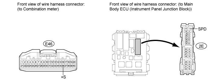
WIRING DIAGRAM
INSPECTION PROCEDURE
CHECK CAN COMMUNICATION SYSTEM
CHECK SPEEDOMETER OPERATION
READ VALUE USING TECHSTREAM (VEHICLE SPEED SIGNAL)
CHECK HARNESS AND CONNECTOR (COMBINATION METER - INSTRUMENT PANEL JUNCTION BLOCK)
INSPECT COMBINATION METER
DTC B2282 Vehicle Speed Signal Malfunction |
DTC B2283 Vehicle Speed Sensor Malfunction |
DESCRIPTION
The skid control ECU converts these signals into 4-pulse signals and sends them to the combination meter. After this signal is converted into a more precise rectangular waveform by the waveform shaping circuit inside the combination meter, it is then transmitted to the main body ECU (instrument panel junction block). The main body ECU (instrument panel junction block) determines the vehicle speed based on the frequency of these pulse signals.The main body ECU (instrument panel junction block) and the combination meter are connected by a cable and the CAN. DTC B2282 is output when the cable information and CAN information are inconsistent.- HINT:
- When the main body ECU (instrument panel junction block) is replaced with a new one and the cable from the negative (-) battery terminal is connected, the power source mode becomes the IG-ON mode. When the battery is removed and reinstalled, the power source mode that was selected when the battery was removed is restored.
- After the main body ECU (instrument panel junction block) is replaced, perform the registration procedures for the engine immobiliser system (COROLLA_ZRE142 RM000000QYF05AX.html).
DTC No.
| DTC Detection Condition
| Trouble Area
|
B2282
| Cable information and CAN information between the main body ECU (instrument panel junction block) and the combination meter are inconsistent
| - CAN communication system
- Combination meter system
- Main body ECU (instrument panel junction block)
- Wire harness or connector
|
B2283
| When either of conditions below is met:
- Over-deceleration in vehicle speed
- Vehicle speed and engine speed do not match
| - DTC B2282 detection area
- Combination meter
- Speed sensor
- Skid control ECU
- Main body ECU (instrument panel junction block)
- Wire harness or connector
|
WIRING DIAGRAM
- HINT:
- A voltage of 12 V or 5 V is output from each ECU and then input to the combination meter. The signal is changed to a pulse signal at the transistor in the combination meter. Each ECU controls the respective system based on the pulse signal.
- If a short occurs in an ECU, all systems in the diagram above will not operate normally.
INSPECTION PROCEDURE
| 1.CHECK CAN COMMUNICATION SYSTEM |
Check for CAN communication system DTCs (COROLLA_ZRE142 RM000000WI60ACX.html).
- HINT:
- If the DTCs for the CAN communication system malfunction are output, inspect those DTCs first.
- Result:
Result
| Proceed to
|
CAN communication DTC is not output
| A
|
CAN communication DTC is output
| B
|
| 2.CHECK SPEEDOMETER OPERATION |
Connect the Techstream to the DLC3.
Turn the engine switch on (IG).
Enter the following menus: Body Electrical / Combination Meter / Data List.
Check the values by referring to the values in the table below.
Combination MeterTester Display
| Measurement Item/Range
| Normal Condition
| Diagnostic Note
|
Vehicle Speed Meter
| Vehicle speed/Min.: 0 km/h (0mph), Max.: 255 km/h (158 mph)
| Almost same as actual speed (When driving)
| -
|
- OK:
- Vehicle speed displayed on the Techstream is almost the same as the actual vehicle speed measured using a speedometer tester (calibrated chassis dynamometer).
| 3.READ VALUE USING TECHSTREAM (VEHICLE SPEED SIGNAL) |
Connect the Techstream to the DLC3.
Turn the engine switch on (IG).
Read the Data List according to the displays on the Techstream.
Main BodyTester Display
| Measurement Item/Range
| Normal Condition
| Diagnostic Note
|
Vehicle Speed Signal
| Vehicle speed signal / STOP or RUN
| STOP: Vehicle is stopped
Run: Vehicle is running
| -
|
- OK:
- "STOP" (Vehicle is stopped) and "OFF" (Vehicle is running) appear on the screen.
Proceed to the next step based on the inspection result.
- Result:
| A |
|
|
|
| REPLACE MAIN BODY ECU (INSTRUMENT PANEL JUNCTION BLOCK) |
|
| 4.CHECK HARNESS AND CONNECTOR (COMBINATION METER - INSTRUMENT PANEL JUNCTION BLOCK) |
Disconnect the E46 meter connector.
Disconnect the 2E connector.
Measure the resistance according to the value(s) in the table below.
- Standard Resistance:
Tester Connection
| Condition
| Specified Condition
|
2E-1 (SPD) - E46-36 (+S)
| Always
| Below 1 Ω
|
2E-1 (SPD) or E46-36 (+S) - Body ground
| Always
| 10 kΩ or higher
|
| | REPAIR OR REPLACE HARNESS OR CONNECTOR (COMBINATION METER - INSTRUMENT PANEL JUNCTION BLOCK) |
|
|
| 5.INSPECT COMBINATION METER |
Check the output waveform.
Remove the combination meter with the connector(s) still connected (COROLLA_ZRE142 RM0000024D7032X.html).
Connect the oscilloscope to terminals E46-36 (+S) and body ground.
Turn the engine switch on (IG).
Turn the wheel slowly.
Check the signal waveform according to the condition(s) in the table below.
Item
| Condition
|
Tool setting
| 5 V/DIV., 20 ms./DIV
|
Vehicle condition
| Driving at approx. 20 km/h
|
- OK:
- The waveform is displayed as shown in the illustration.
- HINT:
- When the system is functioning normally, one wheel revolution generates 4 pulses. As the vehicle speed increases, the width indicated by (A) in the illustration narrows.
| OK |
|
|
|
| REPLACE MAIN BODY ECU (INSTRUMENT PANEL JUNCTION BLOCK) |
|