Toyota Parking Assist-Sensor System Clearance Sonar Main Switch Circuit
DESCRIPTION
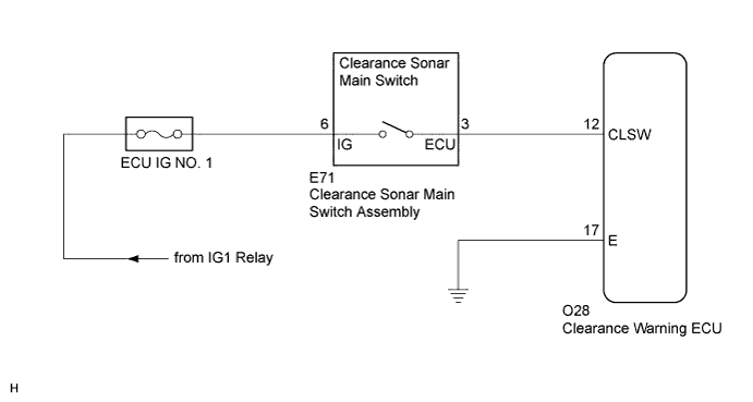
WIRING DIAGRAM
INSPECTION PROCEDURE
READ VALUE USING INTELLIGENT TESTER
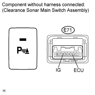
INSPECT CLEARANCE SONAR MAIN SWITCH ASSEMBLY
CHECK HARNESS AND CONNECTOR (CLEARANCE SONAR MAIN SWITCH - BATTERY)
CHECK HARNESS AND CONNECTOR (CLEARANCE SONAR MAIN SWITCH - ECU)
TOYOTA PARKING ASSIST-SENSOR SYSTEM - Clearance Sonar Main Switch Circuit |
DESCRIPTION
The clearance sonar main switch assembly is installed at the base of the driver side instrument panel.When the clearance sonar main switch is turned on, an ON signal is sent to the clearance warning ECU. The Toyota parking assist-sensor system operates according to this signal.WIRING DIAGRAM
INSPECTION PROCEDURE
| 1.READ VALUE USING INTELLIGENT TESTER |
Connect the intelligent tester to the DLC3.
Turn the ignition switch to ON.
Turn the intelligent tester on.
Enter the following menus: Body / Clearance Sonar / Data List.
Check the Data List for proper functioning of the following items.
Clearance SonarTester Display
| Measurement Item/Range
| Normal Condition
| Diagnostic Note
|
Main Switch
| Clearance sonar main switch/OFF or ON
| OFF: Clearance sonar main switch off
ON: Clearance sonar main switch on with indicator illuminated
| -
|
Clearance Sonar ECU
| ECU information/Normal or Abnormal
| Normal: ECU normal
Abnormal: ECU not normal
| -
|
- Result:
Result
| Proceed to
|
Both of the following conditions are met:
- The display changes as shown above when the clearance sonar main switch is operated.
- "Normal" is displayed.
| A
|
"Normal" is not displayed.
| B
|
Both of the following conditions are met:
- The display does not change as shown above when the clearance sonar main switch is operated.
- "Normal" is displayed.
| C
|
| 2.INSPECT CLEARANCE SONAR MAIN SWITCH ASSEMBLY |
Remove the clearance sonar main switch assembly (CAMRY_ACV40 RM000003GR8001X.html).
Measure the resistance according to the value(s) in the table below.
- Standard Resistance:
Tester Connection
| Switch Condition
| Specified Condition
|
E71-6 (IG) - E71-3 (ECU)
| Clearance sonar main switch is pushed
| Below 1 Ω
|
E71-6 (IG) - E71-3 (ECU)
| Clearance sonar main switch is not pushed
| 10 kΩ or higher
|
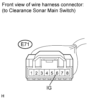
| 3.CHECK HARNESS AND CONNECTOR (CLEARANCE SONAR MAIN SWITCH - BATTERY) |
Measure the voltage according to the value(s) in the table below.
- Standard Voltage:
Tester Connection
| Condition
| Specified Condition
|
E71-6 (IG) - Body ground
| Ignition switch ON
| 11 to 14 V
|
E71-6 (IG) - Body ground
| Ignition switch off
| Below 1 V
|
| | REPAIR OR REPLACE HARNESS OR CONNECTOR |
|
|
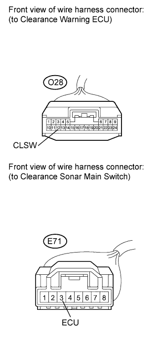
| 4.CHECK HARNESS AND CONNECTOR (CLEARANCE SONAR MAIN SWITCH - ECU) |
Disconnect the clearance warning ECU connector.
Measure the resistance according to the value(s) in the table below.
- Standard Resistance:
Tester Connection
| Condition
| Specified Condition
|
O28-12 (CLSW) - E71-3 (ECU)
| Always
| Below 1 Ω
|
O28-12 (CLSW) - Body ground
| Always
| 10 kΩ or higher
|
| | REPAIR OR REPLACE HARNESS OR CONNECTOR |
|
|