Navigation System Microphone Circuit Between Microphone And Navigation Receiver Assembly
DESCRIPTION
WIRING DIAGRAM
INSPECTION PROCEDURE
INSPECT NAVIGATION RECEIVER ASSEMBLY
CHECK HARNESS AND CONNECTOR (NAVIGATION RECEIVER ASSEMBLY - TELEPHONE MICROPHONE ASSEMBLY)
INSPECT MICROPHONE
NAVIGATION SYSTEM - Microphone Circuit between Microphone and Navigation Receiver Assembly |
DESCRIPTION
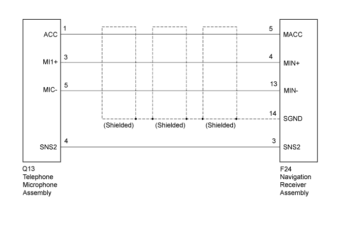
This circuit sends a microphone signal from the telephone microphone assembly to the navigation receiver assembly.It also supplies power from the navigation receiver assembly to the telephone microphone assembly.
WIRING DIAGRAM
INSPECTION PROCEDURE
| 1.INSPECT NAVIGATION RECEIVER ASSEMBLY |
Disconnect the navigation receiver assembly connector.
Measure the voltage according to the value(s) in the table below.
- Standard Voltage:
Tester Connection
| Condition
| Specified Condition
|
F24-5 (MACC) - Body ground
| Ignition switch ACC
| 4 to 6 V
|
Measure the resistance according to the value(s) in the table below.
- Standard Resistance:
Tester Connection
| Condition
| Specified Condition
|
F24-14 (SGND) - Body ground
| Always
| Below 1 Ω
|
F24-13 (MIN-) - Body ground
| Always
| Below 1 Ω
|
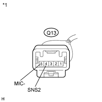
Text in Illustration*1
| Component with harness connected
(Navigation Receiver Assembly)
|
| 2.CHECK HARNESS AND CONNECTOR (NAVIGATION RECEIVER ASSEMBLY - TELEPHONE MICROPHONE ASSEMBLY) |
Disconnect the navigation receiver assembly connector.
Disconnect the telephone microphone assembly connector.
Measure the resistance according to the value(s) in the table below.
- Standard Resistance:
Tester Connection
| Condition
| Specified Condition
|
F24-3 (SNS2) - Q13-4 (SNS2)
| Always
| Below 1 Ω
|
F24-5 (MACC) - Q13-1 (ACC)
| Always
| Below 1 Ω
|
F24-4 (MIN+) - Q13-3 (MI1+)
| Always
| Below 1 Ω
|
F24-13 (MIN-) - Q13-5 (MIC-)
| Always
| Below 1 Ω
|
F24-3 (SNS2) - Body ground
| Always
| 10 kΩ or higher
|
F24-5 (MACC) - Body ground
| Always
| 10 kΩ or higher
|
F24-4 (MIN+) - Body ground
| Always
| 10 kΩ or higher
|
F24-13 (MIN-) - Body ground
| Always
| 10 kΩ or higher
|
F24-14 (SGND) - Body ground
| Always
| 10 kΩ or higher
|
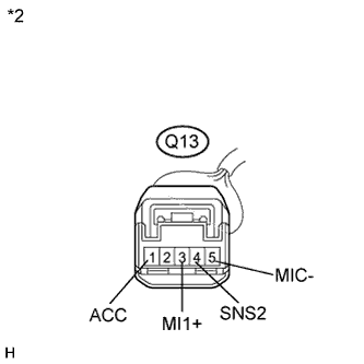
Text in Illustration*1
| Front view of wire harness connector
(to Navigation Receiver Assembly)
|
*2
| Front view of wire harness connector
(to Telephone Microphone Assembly)
|
| | REPAIR OR REPLACE HARNESS OR CONNECTOR |
|
|
Measure the resistance according to the value(s) in the table below.
- Standard Resistance:
Tester Connection
| Condition
| Specified Condition
|
Q13-4 (SNS2) - Q13-5 (MIC-)
| Always
| Below 1 Ω
|
Text in Illustration*1
| Component without harness connected
(Telephone Microphone Assembly)
|