Toyota Parking Assist-Sensor System Clearance Warning Buzzer Circuit
DESCRIPTION
WIRING DIAGRAM
INSPECTION PROCEDURE
CHECK CLEARANCE WARNING BUZZER
CHECK HARNESS AND CONNECTOR (CLEARANCE WARNING ECU - CLEARANCE WARNING BUZZER)
CHECK HARNESS AND CONNECTOR (CLEARANCE WARNING BUZZER - CLEARANCE SONAR MAIN SWITCH)
INSPECT CLEARANCE WARNING BUZZER
CHECK HARNESS AND CONNECTOR (CLEARANCE WARNING ECU - CLEARANCE WARNING BUZZER)
CHECK HARNESS AND CONNECTOR (CLEARANCE WARNING BUZZER - CLEARANCE SONAR MAIN SWITCH)
INSPECT CLEARANCE WARNING BUZZER
TOYOTA PARKING ASSIST-SENSOR SYSTEM - Clearance Warning Buzzer Circuit |
DESCRIPTION
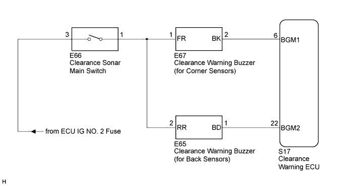
The clearance warning ECU sounds the clearance warning buzzer (for corner sensors) when it receives signals from the corner sensors, and sounds the clearance warning buzzer (for back sensors) when it receives signals from the back sensors.The buzzers sound to alert the driver. The sounding pattern of the buzzers will change according to the distance from an obstacle.
WIRING DIAGRAM
INSPECTION PROCEDURE
| 1.CHECK CLEARANCE WARNING BUZZER |
Check the buzzer which does not sound.
- Result:
Result
| Proceed to
|
Clearance warning buzzer (for Corner Sensors)
| A
|
Clearance warning buzzer (for Back Sensors)
| B
|
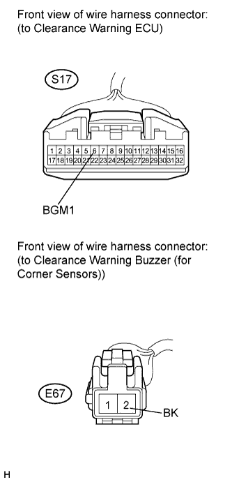
| 2.CHECK HARNESS AND CONNECTOR (CLEARANCE WARNING ECU - CLEARANCE WARNING BUZZER) |
Disconnect the S17 connector from the clearance warning ECU.
Disconnect the E67 connector from the clearance warning buzzer (for corner sensors).
Measure the resistance according to the value(s) in the table below.
- Standard Resistance:
Tester Connection
| Condition
| Specified Condition
|
S17-6 (BGM1) - E67-2 (BK)
| Always
| Below 1 Ω
|
S17-6 (BGM1) - Body ground
| Always
| 10 kΩ or higher
|
| | REPAIR OR REPLACE HARNESS OR CONNECTOR |
|
|
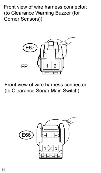
| 3.CHECK HARNESS AND CONNECTOR (CLEARANCE WARNING BUZZER - CLEARANCE SONAR MAIN SWITCH) |
Disconnect the E67 connector from the clearance warning buzzer (for corner sensors).
Disconnect the E66 connector from the clearance sonar main switch.
Measure the resistance according to the value(s) in the table below.
- Standard Resistance:
Tester Connection
| Condition
| Specified Condition
|
E67-1 (FR) - E66-1
| Always
| Below 1 Ω
|
E67-1 (FR) - Body ground
| Always
| 10 kΩ or higher
|
| | REPAIR OR REPLACE HARNESS OR CONNECTOR |
|
|
| 4.INSPECT CLEARANCE WARNING BUZZER |
Replace the clearance warning buzzer (for corner sensors) (CAMRY_ACV40 RM000001PYN00QX.html).
- HINT:
- Since the clearance warning buzzer (for corner sensors) cannot be inspected while it is removed from the vehicle, replace the clearance warning buzzer (for corner sensors) with a known good one and check that the condition returns to normal. This buzzer is an ECU-excited type.
Check the operation of the toyota parking assist-sensor system (CAMRY_ACV40 RM0000012EG00CX.html).
- Result:
Result
| Proceed to
|
Buzzer sound
| A
|
Buzzer does not sound
| B
|
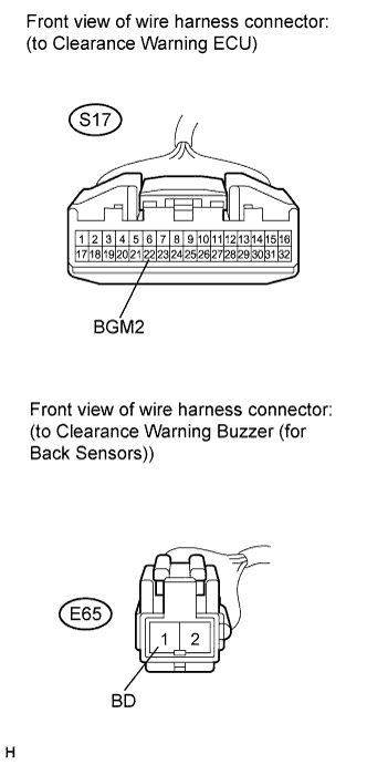
| 5.CHECK HARNESS AND CONNECTOR (CLEARANCE WARNING ECU - CLEARANCE WARNING BUZZER) |
Disconnect the S17 connector from the clearance warning ECU.
Disconnect the E65 connector from the clearance warning buzzer (for back sensors).
Measure the resistance according to the value(s) in the table below.
- Standard Resistance:
Tester Connection
| Condition
| Specified Condition
|
S17-22 (BGM2) - E65-1 (BD)
| Always
| Below 1 Ω
|
S17-22 (BGM2) - Body ground
| Always
| 10 kΩ or higher
|
| | REPAIR OR REPLACE HARNESS OR CONNECTOR |
|
|
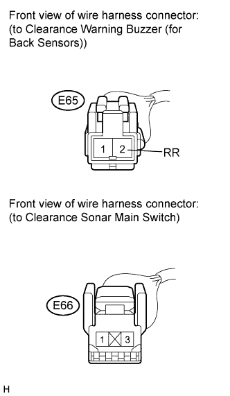
| 6.CHECK HARNESS AND CONNECTOR (CLEARANCE WARNING BUZZER - CLEARANCE SONAR MAIN SWITCH) |
Disconnect the E65 connector from the clearance warning buzzer (for back sensors).
Disconnect the E66 connector from the clearance sonar main switch.
Measure the resistance according to the value(s) in the table below.
- Standard Resistance:
Tester Connection
| Condition
| Specified Condition
|
E65-2 (RR) - E66-1
| Always
| Below 1 Ω
|
E65-2 (RR) - Body ground
| Always
| 10 kΩ or higher
|
| | REPAIR OR REPLACE HARNESS OR CONNECTOR |
|
|
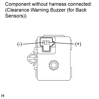
| 7.INSPECT CLEARANCE WARNING BUZZER |
Remove the clearance warning buzzer (for back sensors) (CAMRY_ACV40 RM000001PYN00RX.html).
Apply battery voltage and check the operation of the clearance warning buzzer, as shown in the table below.
- OK:
Measurement Condition
| Specified Condition
|
Battery positive (+) → Terminal 1
Battery negative (-) → Terminal 2
| Operating sound occurs
|
- HINT:
- Replace the clearance warning buzzer when battery voltage is applied and the clearance warning buzzer does not sound because the buzzer is a self-excited type.