Audio And Visual System Microphone Circuit Between Microphone And Radio Receiver
DESCRIPTION
WIRING DIAGRAM
INSPECTION PROCEDURE
INSPECT RADIO RECEIVER
CHECK HARNESS AND CONNECTOR (TELEPHONE MICROPHONE ASSEMBLY - RADIO RECEIVER)
AUDIO AND VISUAL SYSTEM - Microphone Circuit between Microphone and Radio Receiver |
DESCRIPTION
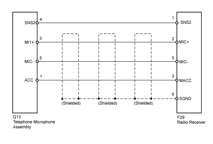
This circuit sends the microphone signal from the telephone microphone assembly to the radio receiver. It also supplies power source from the radio receiver to the telephone microphone assembly.
WIRING DIAGRAM
INSPECTION PROCEDURE
Disconnect the radio receiver connector.
Measure the voltage according to the value(s) in the table below.
- Standard Voltage:
Tester Connection
| Condition
| Specified Condition
|
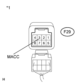
F29-3 (MACC) - Body ground
| Ignition switch to ON
| 4 to 6 V
|
Text in Illustration*1
| Component without harness connected
(Radio Receiver)
|
| 2.CHECK HARNESS AND CONNECTOR (TELEPHONE MICROPHONE ASSEMBLY - RADIO RECEIVER) |
Disconnect the telephone microphone assembly and radio receiver connectors.
Measure the resistance according to the value(s) in the table below.
- Standard Resistance:
Tester Connection
| Condition
| Specified Condition
|
Q13-4 (SNS2) - F29-1 (SNS2)
| Always
| Below 1 Ω
|
Q13-3 (Ml1+) - F29-2 (MIC+)
| Always
| Below 1 Ω
|
Q13-5 (MlC-) - F29-5 (MIC-)
| Always
| Below 1 Ω
|
Q13-1 (ACC) - F29-3 (MACC)
| Always
| Below 1 Ω
|
F29-1 (SNS2) - Body ground
| Always
| 10 kΩ or higher
|
F29-2 (MIC+) - Body ground
| Always
| 10 kΩ or higher
|
F29-5 (MIC-) - Body ground
| Always
| 10 kΩ or higher
|
F29-3 (MACC) - Body ground
| Always
| 10 kΩ or higher
|
F29-6 (SGND) - Body ground
| Always
| 10 kΩ or higher
|
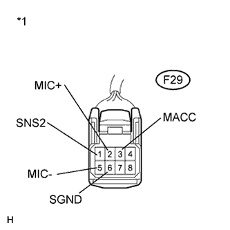
Text in Illustration*1
| Front view of wire harness connector
(to Radio Receiver)
|
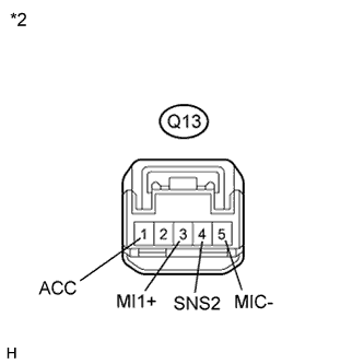
*2
| Front view of wire harness connector
(to Telephone Microphone Assembly)
|
| | REPAIR OR REPLACE HARNESS OR CONNECTOR |
|
|