Dtc B1207 Certification Ecu Communication Malfunction
DESCRIPTION
WIRING DIAGRAM
INSPECTION PROCEDURE
CHECK DTC
CHECK FOR OPEN IN CAN MS BUS MAIN WIRE (CERTIFICATION ECU MAIN WIRE)
CHECK HARNESS AND CONNECTOR (POWER SOURCE CIRCUIT)
DTC B1207 Certification ECU Communication Malfunction |
DESCRIPTION
The main body ECU will store this DTC when no signals can be received from the certification ECU while the CAN MS main bus is normal. DTC No.
| DTC Detection Condition
| Trouble Area
|
B1207
| No communication from certification ECU
| - Certification ECU branch wire or connector
- Certification ECU power source circuit
- Certification ECU
|
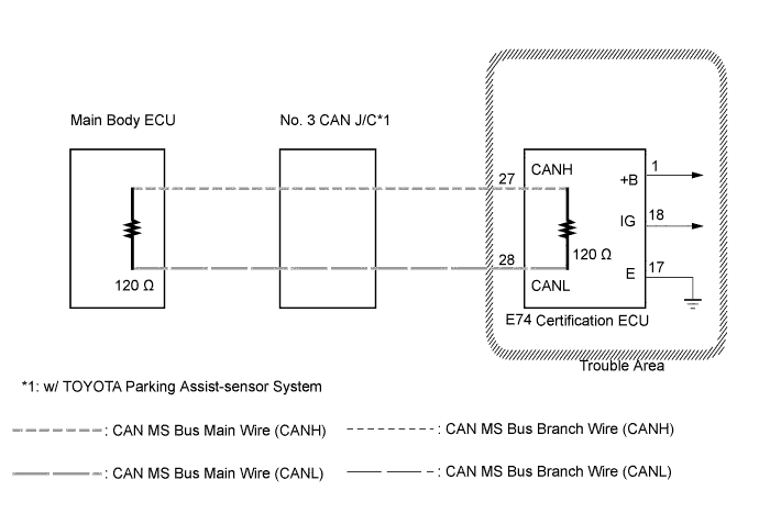
WIRING DIAGRAM
INSPECTION PROCEDURE
- NOTICE:
- Turn the ignition switch off before measuring the resistances of CAN bus main wires and CAN bus branch wires.
- After the ignition switch is turned off, check that the key reminder warning system and lighting system are not operating.
- Before measuring the resistance, leave the vehicle as is for at least 1 minute and do not operate the ignition switch, any other switches, or the doors. If any doors need to be opened in order to check connectors, open the doors and leave them open.
- HINT:
- Operating the ignition switch, any other switches, or a door triggers related ECU and sensor communication on the CAN. This communication will cause the resistance value to change.
Check for DTCs.
- HINT:
- If CAN MS bus communication error DTC B2326 is output, troubleshoot for B2326 and check for malfunctions in the CAN MS main bus circuit (CAMRY_ACV40 RM000002DX8020X.html).
- Result:
Result
| Proceed to
|
B2326 is not output
| A
|
B2326 is output
| B
|
| 2.CHECK FOR OPEN IN CAN MS BUS MAIN WIRE (CERTIFICATION ECU MAIN WIRE) |
Turn the ignition switch off.
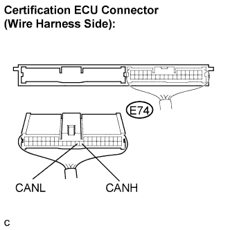
Disconnect connector E74 from the certification ECU.
Measure the resistance according to the value(s) in the table below.
- Standard resistance:
Tester Connection
| Condition
| Specified Value
|
E74-27 (CANH) - E74-28 (CANL)
| Ignition switch off
| 108 to 132 Ω
|
| | REPAIR OR REPLACE CAN MS BUS MAIN WIRE OR CONNECTOR |
|
|
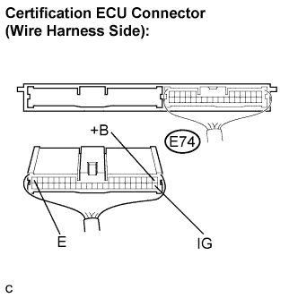
| 3.CHECK HARNESS AND CONNECTOR (POWER SOURCE CIRCUIT) |
Measure the resistance according to the value(s) in the table below.
- Standard resistance:
Tester Connection
| Condition
| Specified Value
|
E74-17 (E) - Body ground
| Always
| Below 1 Ω
|
Measure the voltage according to the value(s) in the table below.
- Standard voltage:
Tester Connection
| Condition
| Specified Value
|
E74-18 (IG) - Body ground
| Ignition switch ON
| 10 to 14 V
|
E74-1 (+B) - Body ground
| Always
| 10 to 14 V
|
| | REPAIR OR REPLACE HARNESS OR CONNECTOR |
|
|
| OK |
|
|
|
| REPLACE CERTIFICATION ECU |
|