Lighting System -- System Description |
| MANUAL LIGHT CONTROL SYSTEM |
The main body ECU controls this system based on the signals listed below.
Input Output Lights that illuminate Light control switch TAIL signal Taillight relay drive signal - Taillights
- License plate lights
- Parking lights
Light control switch HEAD signal Headlight relay drive signal Low beam headlights - Taillights
| AUTOMATIC LIGHT CONTROL SYSTEM |
The main body ECU controls this system based on the signals listed below.
Input Output Lights that illuminate - Light control switch AUTO signal
- Automatic light control sensor signal
- Headlight relay drive signal
- Taillight relay drive signal
- Low beam headlights
- Taillights
- License plate lights
- Parking lights
- Light control switch AUTO signal
| LIGHT AUTO TURN OFF SYSTEM |
The main body ECU controls this system based on the signals listed below.
Input Output Lights that operate - Combination switch signal
- Door courtesy switch signal
- Ignition switch signal
- Headlight relay OFF demand
- Taillight relay OFF demand
- High beam headlight relay OFF demand
- Front fog light relay OFF demand
- Rear fog light relay OFF demand
- Low beam headlights
- Taillights, license plate lights and parking lights
- High beam headlights
- Front fog lights
- Rear fog lights
- Combination switch signal
| ILLUMINATED ENTRY SYSTEM |
The main body ECU controls this system. The operation and condition of the illuminated entry system are described below.
Operation Condition Fade in When either of the following conditions is met, the interior light and ignition key cylinder light*1 / engine switch illumination*2 fade in: - Any door is opened.
- Any door is unlocked when the ignition switch is off and all doors are closed.
- Ignition switch is turned from ACC position to OFF when all doors are closed.
Fade out immediately When either of the following conditions is met, the interior light and ignition key cylinder light*1 / engine switch illumination*2 fade out: - The ignition switch is turned from OFF to the ACC or ON position when all doors are closed.
- All doors are locked when the ignition switch is off.
Illuminate for approximately 15 seconds, and then fade out Any doors are closed when the ignition switch is off. Fade out (Battery saving) When the following conditions are met, the interior light and ignition key cylinder light*1 / engine switch illumination*2 fade out: - A key is not inserted in the ignition key cylinder*1.
- A key is not in the actuation area*2.
- There are no changes in the condition of the doors for 20 minutes.
- HINT:
- *1: without Entry and Start System
- *2: with Entry and Start System
- Any door is opened.
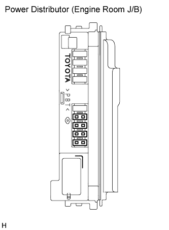
| POWER DISTRIBUTOR |
The power distributor (engine room J/B assembly) is installed in the engine room R/B. The low beam headlight relays and high beam headlight relay are installed in the power distributor.
When a short malfunction occurs between the power distributor and high beam headlight bulbs, the fail-safe function operates.
When the fail-safe function operates, the power distributor stops the operation of the high beam headlight relay.
 |
| HID HEADLIGHT SYSTEM |
Discharge bulbs have the following feature:
- The light emitted by the bulb is close in color to sunlight. The light shines ahead over a broader range and farther forward, increasing the visibility of the driver.
- Discharge bulbs consume less power.
- The light emitted by the bulb is close in color to sunlight. The light shines ahead over a broader range and farther forward, increasing the visibility of the driver.
This system consists of discharge bulbs and the light control ECU. The light control ECU is installed in the headlight assembly.
The light control ECUs transform the voltage that is input from the battery to a high voltage of up to 20,000 V and applies it to the discharge bulbs in order to illuminate them.
A fail-safe function is provided as a countermeasure against the high voltage that is generated in case that a problem occurs in the headlight system.
- NOTICE:
- For safety reasons, do not attempt to measure the voltage output from a light control ECU.
| AUTOMATIC HEADLIGHT BEAM LEVEL CONTROL SYSTEM |
General
- This system maintains the headlight LO beams at a constant level while the vehicle is stopping.
- This system is controlled by the headlight beam level control ECU. This ECU detects the vehicle posture via the rear height control sensor, and detects the vehicle speed via the combination meter. The ECU then controls the headlight leveling motor based on these pieces of information, in order to change the headlight reflector angle.
- NOTICE:
- Initialize the height control sensor signal after the vehicle height changes due to replacement of the suspension or after performing such operations as removal and reinstallation or replacement of the rear height control sensor sub-assembly.
- When the headlight beam level control ECU is replaced, the initialization is also necessary.
- This system maintains the headlight LO beams at a constant level while the vehicle is stopping.
Function and construction of components
Components Function and Construction Rear height control sensor Detects the amount of vehicle height. Combination meter - Outputs the vehicle speed signal to the headlight beam level control ECU.
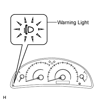
- Warning indicator in the combination meter illuminates for 3 seconds and then goes off when the ignition switch is turned to the ON position (bulb check function).
- Warning indicator in the combination meter illuminates to alert the driver when a malfunction in this system is detected.
Headlight leveling motor Based on the signals received from the headlight beam level control ECU, each motor moves the reflector in the headlight to vary its LO beam. DLC3 The height control sensor signal initialization and headlight leveling motor operation check can be performed via the DLC3. Headlight beam level control ECU - Based on the signals that are transmitted by height control sensor and combination meter, this ECU detects the amount of variance of the vehicle posture while the vehicle is stopped.
- Based on the detected value, this ECU outputs control signals to the headlight leveling motor.
- This ECU turns on the headlight beam level control system warning indicator for 3 seconds when the ignition switch is turned to the ON position (bulb check function).
- This ECU turns on the headlight beam level control system warning indicator to alert the driver when a malfunction in this system is detected.
- Outputs the vehicle speed signal to the headlight beam level control ECU.
Fail-safe function
The headlight beam level control ECU operates in the fail-safe mode if an abnormal condition has been detected, and illuminates the automatic headlight leveling system warning light in the combination meter when a malfunction is detected in the height control sensor.
 |
| MANUAL HEADLIGHT BEAM LEVEL CONTROL SYSTEM |
When the vehicle posture changes in accordance with the number (weight) of passengers and volume of luggage, this system enables the adjustment of the LO beam level (11-step) of the headlights manually to the appropriate level based on the position of the headlight leveling switch.
- The beam level of the headlight can be adjusted by the headlight leveling motor that are installed in the headlight assembly.
- A headlight leveling switch is provided to allow the driver to control this system.
- The beam level of the headlight can be adjusted by the headlight leveling motor that are installed in the headlight assembly.