Condenser -- Installation |
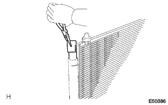
| 1. INSTALL COOLER DRYER |
Using pliers, install the cooler dryer to the modulator.
 |
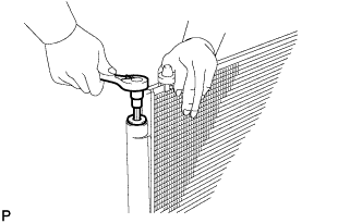
Apply sufficient compressor oil to an O-ring and cap fitting surface.
- Compressor oil:
- ND-OIL 8 or equivalent
 |
Using a straight hexagon wrench 14 mm, install the cap to the cooler condenser core.
- Torque:
- 2.9 N*m{30 kgf*cm, 26 in.*lbf}
 |
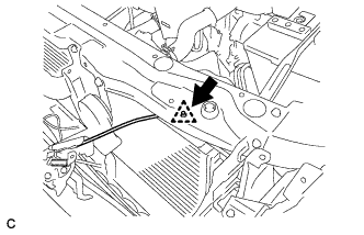
| 2. INSTALL COOLER CONDENSER ASSEMBLY |
Install the cooler condenser assembly with the 4 bolts.
- Torque:
- 5.0 N*m{51 kgf*cm, 44 in.*lbf}
- HINT:
- If the condenser is replaced with a new one, add compressor oil to the new condenser.
- Capacity:
- 40 cc (1.4 fl. oz.)
- Compressor oil:
- ND-8 or equivalent
 |
| 3. INSTALL COOLER REFRIGERANT DISCHARGE PIPE |
Remove the attached vinyl tape from the pipe and the connecting part of the cooler condenser assembly.
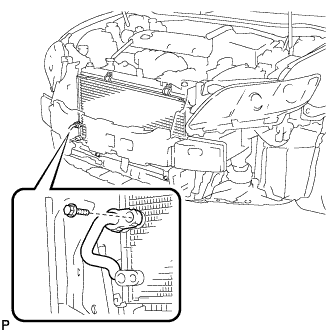 |
Sufficiently apply compressor oil to a new O-ring and the fitting surface of the pipe joint.
- Compressor oil:
- ND-OIL 8 or equivalent
Install the O-ring on the cooler refrigerant discharge pipe.
- Torque:
- 9.8 N*m{100 kgf*cm, 87 in.*lbf}
| 4. INSTALL AIR CONDITIONING TUBE AND ACCESSORY |
Remove the attached vinyl tape from the tube and the connecting part of the cooler condenser assembly.
 |
Sufficiently apply compressor oil to a new O-ring and the fitting surface of the tube joint.
- Compressor oil:
- ND-OIL 8 or equivalent
Install the O-ring on the air conditioning tube assembly.
Install the air conditioning tube assembly on the cooler condenser assembly with the bolt.
- Torque:
- 9.8 N*m{100 kgf*cm, 87 in.*lbf}
| 5. INSTALL HOOD LOCK SUPPORT SUB-ASSEMBLY |
Install the hood lock support sub-assembly with the bolt.
- Torque:
- 7.5 N*m{77 kgf*cm, 66 in.*lbf}
 |
| 6. INSTALL RADIATOR SUPPORT UPPER |
Install the radiator support upper with the 5 bolts.
- Torque:
- 7.0 N*m{71 kgf*cm, 62 in.*lbf}
 |
For LHD:
Install the hood lock control cable assembly to the radiator support upper with the clamp.
For RHD:
Install the hood lock control cable assembly to the radiator support upper with the clamp.

Install the hood lock assembly to the radiator support upper with the 3 bolts.
- Torque:
- 7.5 N*m{77 kgf*cm, 66 in.*lbf}
 |
Connect the horn connector.
| 7. INSTALL FRONT BUMPER ASSEMBLY |
w/ Headlight Cleaner System:
Connect the headlight cleaner washer hose.

Connect each connector.
w/ TOYOTA Parking Assist-sensor System:
Connect the No. 1 ultrasonic sensor connector and engage the clamp.
Engage the 2 claws.
- HINT:
- Use the same procedure for the RH side and LH side.
 |
Install the front bumper assembly with the 8 screws, 2 clips, 2 radiator grille protectors and bolt.
 |
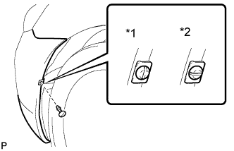
Install the pin hold clip.
- NOTICE:
- Insert the pin hold clip with the slot aligned vertically. Do not rotate the clip after inserting it. After installation, confirm that the slot is vertical.
- HINT:
- Use the same procedure for the RH side and LH side.
 |
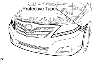
Remove the applied protective tape on the front bumper assembly.
 |
| 8. INSTALL NO. 1 AIR CLEANER INLET (for 2GR-FE) |
Install the No. 1 air cleaner inlet with the bolt.
- Torque:
- 5.0 N*m{51 kgf*cm, 44 in.*lbf}
 |
| 9. INSTALL AIR CLEANER INLET ASSEMBLY (for 2AZ-FE) |
Install the air cleaner inlet with the 2 bolts.
- Torque:
- 5.0 N*m{51 kgf*cm, 44 in.*lbf}
 |
| 10. INSTALL AIR CLEANER INLET SUB-ASSEMBLY (for 2GR-FE) |
Install the air cleaner inlet with the clamp and 2 bolts.
- Torque:
- 5.0 N*m{51 kgf*cm, 44 in.*lbf}
 |
| 11. INSTALL AIR CLEANER CAP SUB-ASSEMBLY (for 2AZ-FE) |
Install the air cleaner filter element onto the air cleaner case.
Insert the hinges. Install the air cleaner cap sub-assembly with the 2 bolts.
 |
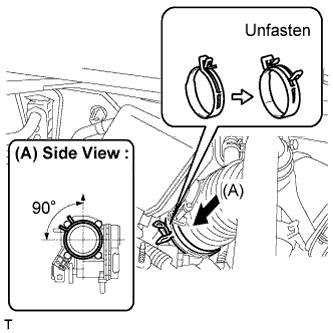
Align the matchmarks of the No. 1 air cleaner hose and throttle body, and then connect the air cleaner hose No. 1 to the throttle body and unfasten the No. 1 air cleaner hose clamp.
- NOTICE:
- Make sure that the hose clamp is at the correct angle.
 |
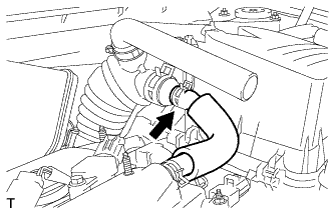
Connect the No. 2 ventilation hose to the air cleaner hose.
 |
Connect the purge line hose to the clamp (*1).
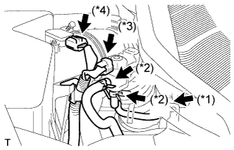 |
Connect the 2 purge VSV vacuum hoses (*2).
Connect the purge VSV connector (*3).
Connect the mass air flow meter connector (*4).
| 12. INSTALL AIR CLEANER CAP SUB-ASSEMBLY (for 2GR-FE) |
Install the air cleaner cap sub-assembly, and connect the 3 bands.
 |
Connect the mass air flow meter connector (*1).
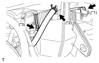 |
Connect the No. 2 ventilation hose (*2).
Connect the hose band (*3).
Connect the 3 vacuum hoses.
 |
| 13. INSTALL COOL AIR INTAKE DUCT SEAL (for 2GR-FE) |
Install the cool air intake duct seal with the 7 clips.
 |
| 14. INSTALL V-BANK COVER SUB-ASSEMBLY (for 2GR-FE) |
Engage the 3 retainers to install the V-bank cover.
 |
| 15. ADD ENGINE COOLANT (for 2AZ-FE) |
Close the radiator drain cock plug and 2 cylinder block drain cock plugs.
- Torque:
- 13 N*m{130 kgf*cm, 9 ft.*lbf} for cylinder block drain cock plug
Slowly fill the radiator with TOYOTA Super Long Life Coolant (SLLC).
- Specified capacity:
- 6.2 liters (6.6 US qts, 5.5 lmp. qts)
- HINT:
- TOYOTA vehicles are filled with TOYOTA SLLC at the factory. In order to avoid damage to the engine cooling system and other technical problems, only use TOYOTA SLLC or similar high quality ethylene glycol based non-silicate, non-amine, non-nitrite, non-borate coolant with long-life hybrid organic acid technology (coolant with long-life hybrid organic acid technology consists of a combination of low phosphates and organic acids).
- Contact your TOYOTA dealer for further details.
Slowly pour coolant into the radiator reservoir tank until it reaches the FULL line.
Press the inlet and outlet radiator hoses several times by hand, and then check the level of the coolant.
If the coolant level is low, add coolant.
Install the radiator cap sub-assembly and reservoir tank cap.
Start the engine, and warm it up.
- HINT:
- Adjust the air conditioner set temperature to MAX (HOT).
Stop the engine, and wait until the engine coolant cools down.
Add engine coolant to the FULL line on the radiator reservoir.
| 16. ADD ENGINE COOLANT (for 2GR-FE) |
Close the radiator drain cock plug and 2 cylinder block drain cock plugs.
- Torque:
- 13 N*m{130 kgf*cm, 9 ft.*lbf} for cylinder block drain cock plug
Slowly fill the radiator with TOYOTA Super Long Life Coolant (SLLC).
- Specified capacity:
- 9.0 liters (9.5 US qts, 7.9 lmp. qts)
- HINT:
- TOYOTA vehicles are filled with TOYOTA SLLC at the factory. In order to avoid damage to the engine cooling system and other technical problems, only use TOYOTA SLLC or similar high quality ethylene glycol based non-silicate, non-amine, non-nitrite, non-borate coolant with long-life hybrid organic acid technology (coolant with long-life hybrid organic acid technology consists of a combination of low phosphates and organic acids).
- Contact your TOYOTA dealer for further details.
Slowly pour coolant into the radiator reservoir tank until it reaches the FULL line.
Press the inlet and outlet radiator hoses several times by hand, and then check the level of the coolant.
If the coolant level is low, add coolant.
Install the radiator cap sub-assembly and reservoir tank cap.
Start the engine, and warm it up.
- HINT:
- Adjust the air conditioner set temperature to MAX (HOT).
Stop the engine, and wait until the engine coolant cools down.
Add engine coolant to the FULL line on the radiator reservoir.
| 17. CHECK FOR ENGINE COOLANT LEAKS |
| 18. CHARGE WITH REFRIGERANT |
Perform vacuum purging using a vacuum pump.
Charge with refrigerant HFC-134a (R134a).

- Standard:
- 450 to 550 g (15.9 to 19.4 oz.)
- SST
- 07110-58060(07117-58060,07117-58070,07117-58080,07117-58090,07117-78050,07117-88060,07117-88070,07117-88080)
- NOTICE:
- Do not turn the A/C on before charging with refrigerant. Doing so will cause the cooler compressor to work without refrigerant, resulting in overheating of the cooler compressor.
- Approximately 100 g (3.53 oz.) of refrigerant may need to be charged after bubbles disappear.
The refrigerant amount should be checked by quantity, not with the sight glass.
- HINT:
- Ensure that sufficient refrigerant is available to recharge the system when using a refrigerant recovery unit. Refrigerant recovery units are not always able to recover 100 % of the refrigerant from an A/C system.
| 19. WARM UP ENGINE |
Keep the A/C switch on for at least 2 minutes to warm up the compressor.
- NOTICE:
- Be sure to warm up the compressor when turning the A/C on after removing and installing the cooler refrigerant lines (including the compressor), to prevent damage to the compressor.
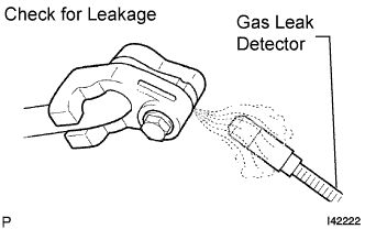
| 20. CHECK FOR REFRIGERANT LEAKS |
After recharging with refrigerant gas, check for leakage of refrigerant gas using a halogen leak detector.
Carry out the test under the following conditions:
- IG OFF
- Secure good ventilation (the gas leak detector may react to volatile gases which are not refrigerant, such as evaporated gasoline and exhaust gas).
- Repeat the test 2 or 3 times.
- Make sure that there is some refrigerant remaining in the refrigeration system.
When the compressor is off: approx. 392 to 588 kPa (4 to 6 kgf/cm2, 57 to 85 psi)
- IG OFF
Using a gas leak detector, check for leakage from the refrigerant lines.
 |
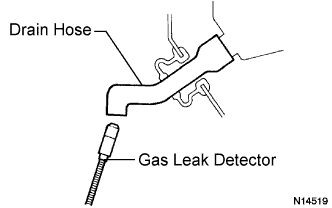
Bring the gas leak detector close to the drain hose with the detector's power off, and then turn the detector on.
- HINT:
- After the blower motor has stopped, let the cooling unit stand for more than 15 minutes.
- Bring the gas leak detector sensor under the drain hose.
- When bringing the gas leak detector close to the drain hose, make sure that the gas leak detector does not react to volatile gases.
If it is not possible to avoid interference from volatile gases, the vehicle should be lifted up to allow testing.
 |
If a gas leak is not detected from the drain hose, remove the blower motor control from the cooling unit. Insert the gas leak detector sensor into the unit and perform the test.
Disconnect the pressure switch connector and leave it for approximately 20 minutes. Bring the gas leak detector close to the pressure switch and perform the test.
| 21. VEHICLE PREPARATION FOR FOG LIGHT AIM ADJUSTMEN (w/ Fog Light) |
Prepare the vehicle:
- Ensure there is no damage or deformation to the body around the fog lights.
- Fill the fuel tank.
- Make sure that the oil is filled to the specified level.
- Make sure that the engine coolant is filled to the specified level.
- Inflate the tires to the appropriate pressure.
- Unload the trunk and vehicle, ensuring that the spare tire, tools, and jack are in their original positions.
- Sit a person of average weight (75 kg, 165 lb) in the driver's seat.
- Vehicles with height adjustable suspension should set the vehicle height to the lowest setting prior to adjusting the fog light aim.
- Ensure there is no damage or deformation to the body around the fog lights.
| 22. PREPARATION FOR FOG LIGHT AIMING (w/ Fog Light) |
Prepare the vehicle:
- Place the vehicle in a location that is dark enough to clearly observe the cutoff line. The cutoff line is a distinct line, below which light from the fog lights can be observed and above which it cannot.
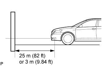
- Place the vehicle at a 90° angle to the wall.
- Create a 25 m (82 ft) distance between the vehicle (fog light bulb center) and the wall.
- Make sure that the vehicle is on a level surface.
- Bounce the vehicle up and down to settle the suspension.
- NOTICE:
- A distance of 25 m (82 ft) between the vehicle (fog light bulb center) and the wall is necessary for proper aim adjustment. If sufficient space is not available, secure a distance of exactly 3 m (9.84 ft) to allow for checking and adjustment of fog light aim. (The size of the target zone will change with the distance, so follow the instructions in the illustration.)
- Place the vehicle in a location that is dark enough to clearly observe the cutoff line. The cutoff line is a distinct line, below which light from the fog lights can be observed and above which it cannot.
 |
Prepare a piece of thick white paper (approximately 2 m (6.6 ft) (height) x 4 m (13.1 ft) (width)) to use as a screen.
Draw a vertical line down the center of screen (V line).
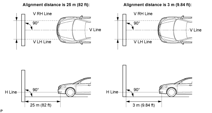
Set the screen as shown in the illustration.
- HINT:
- Stand the screen perpendicular to the ground.
- Align the V line on the screen with the center of the vehicle.
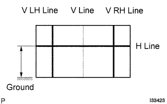
Draw base lines (H, V LH, and V RH lines) on the screen as shown in the illustration.
- HINT:
- Mark the fog light bulb center marks on the screen. If the center mark cannot be observed on the fog light, use the center of the fog light bulb or the manufacturer's name marked on the fog light as the center mark.
H Line (Fog light height):
Draw a horizontal line across the screen so that it passes through the center marks. The H line should be at the same height as the fog light bulb center marks of the low-beam fog lights.V LH Line, V RH Line (Center mark position of left-hand (LH) and right-hand (RH) fog lights):
Draw two vertical lines so that they intersect the H line at each center mark.
 |
| 23. FOG LIGHT AIMING INSPECTION (w/ Fog Light) |
Cover the fog light or disconnect the connector of the fog light on the opposite side to prevent light from the fog light that is not being inspected from affecting the fog light aiming inspection.
- NOTICE:
- Do not keep the fog light covered for more than 3 minutes. The fog light lens is made of synthetic resin, which may melt or be damaged due to excessive heat.
Start the engine.
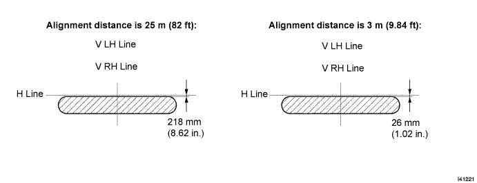
Turn on the fog light and check if the cut off line falls within the specified area in the following illustration.
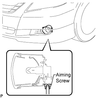
| 24. FOG LIGHT AIMING ADJUSTMENT (w/ Fog Light) |
Adjust the aim vertically:
Adjust the aim of each fog light to the specified range by turning each aiming screw with a screwdriver.- NOTICE:
- The final turn of the aiming screw should be made in the clockwise direction. If the screw is tightened excessively, loosen it and then retighten it, so that the final turn of the screw is in the clockwise direction.
- HINT:
- If it is not possible to correctly adjust fog light aim, check bulb, fog light unit, and fog light unit reflector installation.
 |