Unlock Warning Switch Installation
INSTALL UNLOCK WARNING SWITCH ASSEMBLY
INSTALL IGNITION SWITCH LOCK CYLINDER ASSEMBLY
INSPECT STEERING LOCK OPERATION
INSTALL STEERING COLUMN UPPER WITH SWITCH BRACKET ASSEMBLY
INSTALL TRANSPONDER KEY AMPLIFIER
INSTALL STEERING COLUMN ASSEMBLY
INSTALL NO. 1 AIR DUCT
PLACE FRONT WHEELS FACING STRAIGHT AHEAD
INSTALL TURN SIGNAL SWITCH ASSEMBLY WITH SPIRAL CABLE SUB-ASSEMBLY
INSTALL STEERING COLUMN COVER
ADJUST SPIRAL CABLE SUB-ASSEMBLY
INSTALL STEERING WHEEL ASSEMBLY
INSPECT STEERING WHEEL CENTER POINT
INSTALL STEERING PAD
INSTALL LOWER NO. 2 STEERING WHEEL COVER
INSTALL LOWER NO. 3 STEERING WHEEL COVER
INSTALL LOWER INSTRUMENT PANEL FINISH PANEL LH
INSTALL COWL SIDE TRIM SUB-ASSEMBLY LH
INSTALL FRONT DOOR SCUFF PLATE LH
INSTALL FRONT WHEEL LH
CONNECT CABLE TO NEGATIVE BATTERY TERMINAL
INSPECT STEERING PAD
INSPECT SRS WARNING LIGHT
Unlock Warning Switch -- Installation |
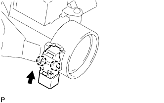
| 1. INSTALL UNLOCK WARNING SWITCH ASSEMBLY |
Engage the 2 claws to install the unlock warning switch assembly to the steering lock sub-assembly.
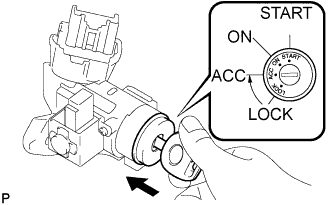
| 2. INSTALL IGNITION SWITCH LOCK CYLINDER ASSEMBLY |
Make sure that the ignition switch lock cylinder assembly is in the ACC position.
Install the ignition switch lock cylinder assembly to the steering lock sub-assembly.
Make sure that the ignition switch lock cylinder assembly is securely installed.
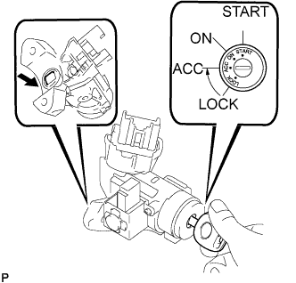
| 3. INSPECT STEERING LOCK OPERATION |
Check that the steering lock mechanism is activated when the key is removed.
Check that the steering lock mechanism is deactivated when the key is inserted and turned to the ACC position.
- HINT:
- If there is any abnormality, replace the ignition switch lock cylinder assembly.
| 4. INSTALL STEERING COLUMN UPPER WITH SWITCH BRACKET ASSEMBLY |
Temporarily install the assembled steering lock and its bracket to the steering column assembly using 2 new tapered-head bolts.
Tighten the 2 tapered-head bolts until the bolt heads break off.
| 5. INSTALL TRANSPONDER KEY AMPLIFIER |
Align the transponder key amplifier with the upper bracket. Tilt the amplifier slightly and slide it into position.
Push the transponder key amplifier to install it to the upper bracket.
- NOTICE:
- Do not push the amplifier with excessive force.
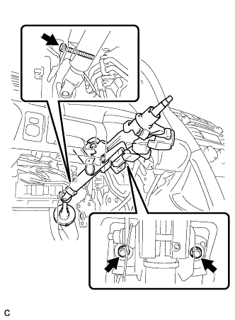
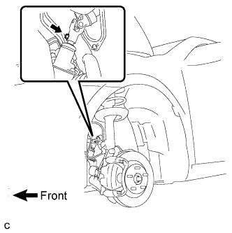
| 6. INSTALL STEERING COLUMN ASSEMBLY |
Install the steering column assembly with the bolt and 2 nuts.
- Torque:
- 21 N*m{214 kgf*cm, 15 ft.*lbf}
Connect the connectors and wire harness clamps to the steering column assembly.
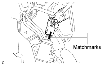
Align the matchmarks on the steering intermediate shaft assembly and the power steering link assembly.
Install the bolt.
- Torque:
- 35 N*m{360 kgf*cm, 26 ft.*lbf}
Install the clamp to the steering column hole shield.
| 7. INSTALL NO. 1 AIR DUCT |
Engage the 2 claws to install the No. 1 air duct.
| 8. PLACE FRONT WHEELS FACING STRAIGHT AHEAD |
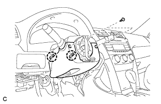
| 9. INSTALL TURN SIGNAL SWITCH ASSEMBLY WITH SPIRAL CABLE SUB-ASSEMBLY |
Install the turn signal switch assembly with spiral cable sub-assembly to the steering column assembly with the clamp.
Connect the connectors to the turn signal switch assembly with spiral cable sub-assembly.
| 10. INSTALL STEERING COLUMN COVER |
Engage the claw to install the upper steering column cover.
Engage the 2 claws to install the lower steering column cover.
Install the 2 screws.
- Torque:
- 2.0 N*m{20 kgf*cm, 18 in.*lbf}
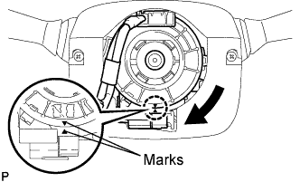
| 11. ADJUST SPIRAL CABLE SUB-ASSEMBLY |
Check that the ignition switch is off.
Check that the battery negative (-) cable is disconnected.
- CAUTION:
- Wait for 90 seconds after disconnecting the cable to prevent airbag deployment.
Rotate the spiral cable counterclockwise slowly by hand until it feels firm.
- NOTICE:
- Do not turn the spiral cable by the airbag wire harness.
Rotate the spiral cable clockwise approximately 2.5 turns to align the marks.
- NOTICE:
- Do not turn the spiral cable by the airbag wire harness.
- HINT:
- The spiral cable will rotate approximately 2.5 turns to both the left and right from the center.
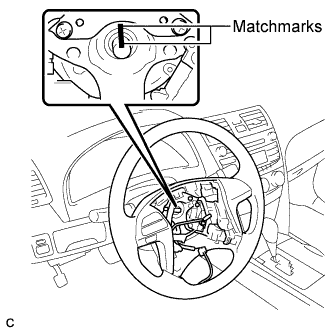
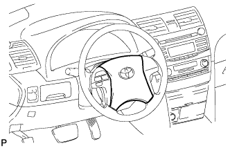
| 12. INSTALL STEERING WHEEL ASSEMBLY |
Align the matchmarks on the steering wheel assembly and steering main shaft.
Install the steering wheel assembly set nut.
- Torque:
- 50 N*m{510 kgf*cm, 37 ft.*lbf}
Connect the connectors to the spiral cable sub-assembly.
| 13. INSPECT STEERING WHEEL CENTER POINT |
Check that the ignition switch is off.
Check that the battery negative (-) terminal is disconnected.
- CAUTION:
- Wait for 90 seconds after disconnecting the cable to prevent airbag deployment.
Support the steering pad with one hand.
Connect the 2 airbag connectors to the steering pad.
- NOTICE:
- When handling the airbag connector, take care not to damage the airbag wire harness.
Connect the horn connector to the steering pad.
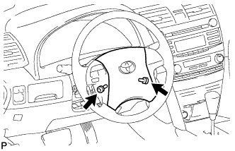
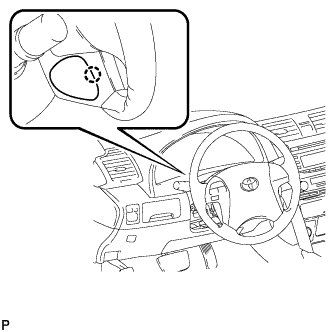
Confirm that the circumference groove of the "TORX" screw fits in the screw case, and place the steering pad onto the steering wheel assembly.
Using a "TORX" socket (T30), tighten the 2 "TORX" screws.
- Torque:
- 8.8 N*m{90 kgf*cm, 78 in.*lbf}
| 15. INSTALL LOWER NO. 2 STEERING WHEEL COVER |
Engage the claw and install the No. 2 lower steering wheel cover.
| 16. INSTALL LOWER NO. 3 STEERING WHEEL COVER |
Engage the claw and install the No. 3 lower steering wheel cover.
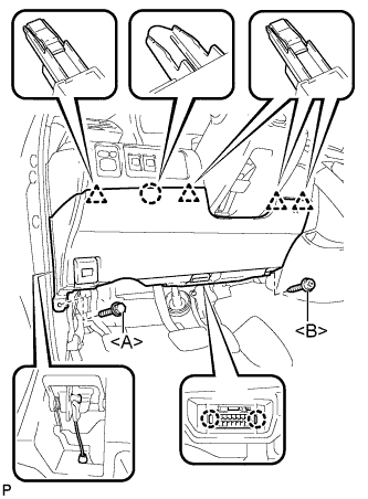
| 17. INSTALL LOWER INSTRUMENT PANEL FINISH PANEL LH |
Install the air hose and connect the connector.
Engage the 2 claws and the DLC3.
Engage the claw and the 4 clips.
Instal the lower instrument panel finish panel LH with the screw <B> and bolt <A>.
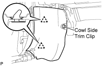
| 18. INSTALL COWL SIDE TRIM SUB-ASSEMBLY LH |
Engage the 2 clips.
Install the cowl side trim sub-assembly LH with the cowl side trim clip.
| 19. INSTALL FRONT DOOR SCUFF PLATE LH |
Engage the 7 claws and 3 clips, then install the front door scuff plate LH.
| 20. INSTALL FRONT WHEEL LH |
- Torque:
- 103 N*m{1,050 kgf*cm, 76 ft.*lbf}
| 21. CONNECT CABLE TO NEGATIVE BATTERY TERMINAL |
With the steering pad installed on the vehicle, perform a visual check. If there are any defects as mentioned below, replace the steering pad with a new one:
- Cuts, minute cracks or marked discoloration on the steering pad top surface or in the grooved portion.
Make sure that the horn sounds.
- HINT:
- If the horn does not sound, inspect the horn system (CAMRY_ACV40 RM0000016F504PX.html).
| 23. INSPECT SRS WARNING LIGHT |
(CAMRY_ACV40 RM000000XFD0BDX.html)