Automatic Transaxle System Ecu Power Source Circuit
DESCRIPTION
WIRING DIAGRAM
INSPECTION PROCEDURE
INSPECT ECU TERMINAL VOLTAGE (+B TERMINAL)
CHECK HARNESS AND CONNECTOR (TCM - BODY GROUND)
AUTOMATIC TRANSAXLE SYSTEM - ECU Power Source Circuit |
DESCRIPTION
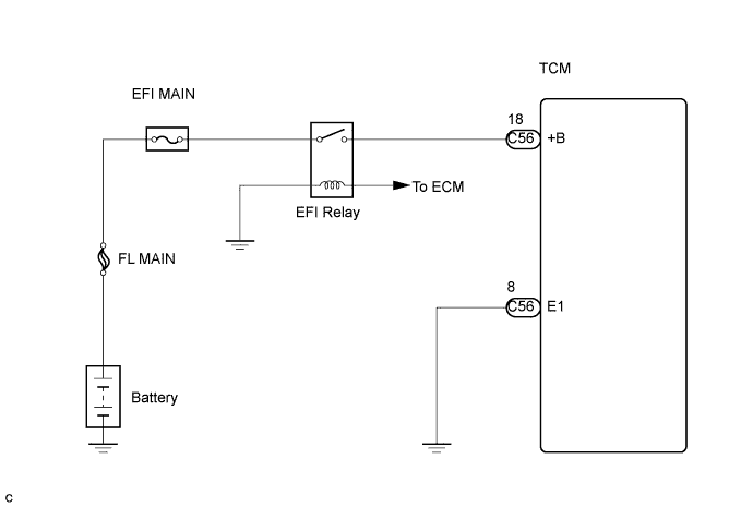
When the ignition switch is turned on, voltage from the ECM's MREL terminal is applied to the EFI relay. This causes the contacts of the EFI relay to close, which supplies power to terminal +B of the TCM.
WIRING DIAGRAM
INSPECTION PROCEDURE
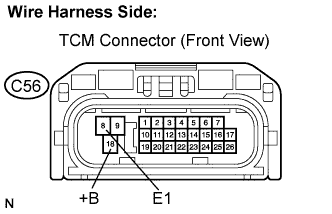
| 1.INSPECT ECU TERMINAL VOLTAGE (+B TERMINAL) |
Disconnect the TCM connector.
Turn the ignition switch on.
Measure the voltage according to the value(s) in the table below.
- Standard voltage:
Tester Connection
| Specified Condition
|
+B (C56-18) - E1 (C56-8)
| 9 to 14 V
|
| | CHECK FOR INTERMITTENT PROBLEMS |
|
|
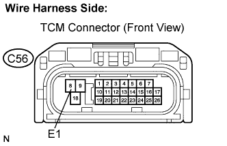
| 2.CHECK HARNESS AND CONNECTOR (TCM - BODY GROUND) |
Measure the resistance according to the value(s) in the table below.
- Standard resistance:
Tester Connection
| Specified Condition
|
E1 (C56-8) - Body ground
| Below 1 Ω
|
Reconnect the TCM connector.
| | REPAIR OR REPLACE HARNESS OR CONNECTOR (TCM - BODY GROUND) |
|
|
| OK |
|
|
|
| REPAIR OR REPLACE HARNESS OR CONNECTOR (TCM - EFI RELAY) |
|