INSTALL NO. 4 PARKING BRAKE CABLE ASSEMBLY (for Automatic Transaxle)
CONNECT NO. 2 PARKING BRAKE CABLE ASSEMBLY (for Automatic Transaxle)
CONNECT NO. 3 PARKING BRAKE CABLE ASSEMBLY (for Automatic Transaxle)
INSTALL CROSS MEMBER FLOOR NO. 4 REINFORCEMENT SUB-ASSEMBLY (for Automatic Transaxle)
INSTALL FRONT FLOOR CARPET ASSEMBLY (for Automatic Transaxle)
INSTALL LUGGAGE DOOR LOCK OPEN LEVER SUB-ASSEMBLY (for Automatic Transaxle)
INSTALL FRONT FLOOR CAUTION PLATE COVER (for Automatic Transaxle)
INSTALL LOWER CENTER PILLAR GARNISH LH (for Automatic Transaxle)
INSTALL REAR DOOR OPENING TRIM WEATHERSTRIP LH (for Automatic Transaxle)
INSTALL FRONT DOOR OPENING TRIM WEATHERSTRIP LH (for Automatic Transaxle)
INSTALL LOWER CENTER PILLAR GARNISH RH (for Automatic Transaxle)
INSTALL REAR DOOR OPENING TRIM WEATHERSTRIP RH (for Automatic Transaxle)
INSTALL FRONT DOOR OPENING TRIM WEATHERSTRIP RH (for Automatic Transaxle)
INSTALL NO. 1 PARKING BRAKE CABLE ASSEMBLY (for Automatic Transaxle)
INSTALL NO. 1 PARKING BRAKE CABLE ASSEMBLY (for Manual Transaxle)
INSTALL PARKING BRAKE PEDAL ASSEMBLY (for Automatic Transaxle)
INSTALL PARKING BRAKE LEVER SUB-ASSEMBLY (for Manual Transaxle)
INSPECT PARKING BRAKE PEDAL TRAVEL (for Automatic Transaxle)
Parking Brake Cable -- Installation |
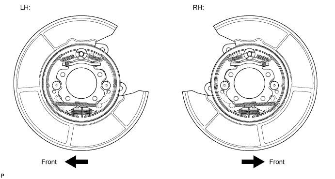
| 1. INSTALL NO. 3 PARKING BRAKE CABLE ASSEMBLY |
Install the parking brake cable clamp to the No. 3 parking brake cable assembly.
 |
Install the No. 3 parking brake cable assembly with 3 bolts (A), bolt (B) and nut (C), and engage each claw.
- Torque:
- Bolt (A):
- 8.5 N*m{87 kgf*cm, 75 in.*lbf}
- Bolt (B) and Nut (C):
- 6.0 N*m{61 kgf*cm, 53 in.*lbf}
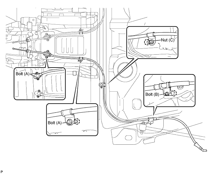
Install the No. 3 parking brake cable assembly to the backing plate with the 2 bolts.
- Torque:
- 8.0 N*m{82 kgf*cm, 71 in.*lbf}
 |
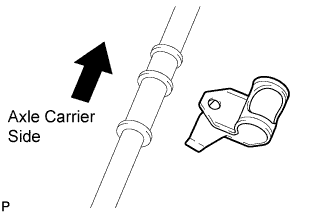
Using a brass bar and a hammer, install the clip to the No. 3 parking brake cable assembly.
 |
| 2. INSTALL NO. 2 PARKING BRAKE SHOE ASSEMBLY |
Using needle-nose pliers, connect the No. 3 parking brake cable assembly to the parking brake shoe lever.
 |
Install the No. 2 parking brake shoe assembly with the parking brake shoe hold down spring No. 2 pin, the parking brake shoe hold down spring No. 2 cup, the parking brake shoe hold down spring and the parking brake shoe hold down spring No. 1 cup.
 |
Engage the claw of the parking brake shoe hold down spring No. 1 cup to the No. 2 parking brake shoe assembly.
| 3. INSTALL PARKING BRAKE SHOE ADJUSTING SCREW SET |
Apply high temperature grease to the parking brake adjusting screw as shown in the illustration.
 |
Install the parking brake shoe return tension No. 2 spring to the No. 1 parking brake shoe assembly and the No. 2 parking brake shoe assembly.
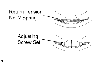 |
Install the parking brake shoe adjusting screw set to the No. 1 parking brake shoe assembly and the No. 2 parking brake shoe assembly.
| 4. INSTALL NO. 1 PARKING BRAKE SHOE ASSEMBLY |
Install the No. 1 parking brake shoe assembly with the parking brake shoe hold down spring No. 1 pin, parking brake shoe hold down spring No. 2 cup, parking brake shoe hold down spring and parking brake shoe hold down spring No. 1 cup.
 |
| 5. INSTALL PARKING BRAKE SHOE STRUT |
Attach the parking brake shoe strut and the parking brake shoe strut compression spring to the No. 1 parking brake shoe assembly and No. 2 parking brake shoe assembly.
| 6. INSTALL PARKING BRAKE SHOE RETURN TENSION NO. 1 SPRING |
Using needle-nose pliers, install the 2 parking brake shoe return tension No. 1 springs.
- HINT:
- First install the front side spring and then the rear side spring.
 |
| 7. CHECK PARKING BRAKE INSTALLATION |
Check that each part is installed properly.
- NOTICE:
- There should be no oil or grease on the friction surface of the shoe lining and disc.
| 8. INSTALL REAR DISC |
Align the matchmarks and install the rear disc.
| 9. ADJUST PARKING BRAKE SHOE CLEARANCE |
Temporarily install the hub nuts.
Remove the shoe adjusting hole plug.
Turn the shoe adjuster and expand the shoe until the disc locks.
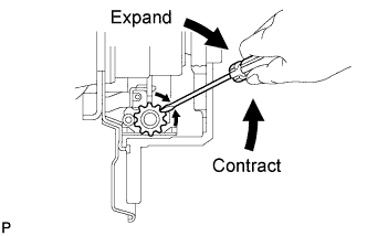 |
Turn and contract the shoe adjuster until the disc can rotate smoothly.
- Standard:
- Return 8 notches.
Check that there is no brake drag against the shoe.
Install the shoe adjusting hole plug.
Remove the hub nuts.
| 10. INSTALL REAR DISC BRAKE CALIPER ASSEMBLY |
Install the rear disc brake caliper assembly with the 2 bolts.
- Torque:
- 62 N*m{632 kgf*cm, 46 ft.*lbf}
 |
| 11. INSTALL REAR WHEEL |
- Torque:
- 103 N*m{1,050 kgf*cm, 76 ft.*lbf}
| 12. INSTALL NO. 2 FRONT FLOOR HEAT LOWER INSULATOR (for 2AZ-FE) |
Install the No. 2 front floor heat lower insulator with the 3 nuts.
- Torque:
- 4.9 N*m{50 kgf*cm, 43 in.*lbf}
 |
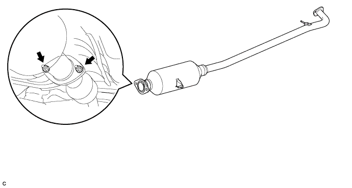
| 13. INSTALL CENTER EXHAUST PIPE ASSEMBLY (for 2AZ-FE) |
Install a new gasket onto the front exhaust pipe.
Install the center exhaust pipe assembly with the 2 bolts and 2 nuts.
- Torque:
- 43 N*m{438 kgf*cm, 32 ft.*lbf}
| 14. INSTALL EXHAUST CENTER PIPE ASSEMBLY (for 2GR-FE) |
Install a new gasket to the exhaust center pipe assembly.
Install the exhaust center pipe to the exhaust front pipe with the 2 nuts and 2 bolts.

- Torque:
- 56 N*m{571 kgf*cm, 41 ft.*lbf}
| 15. INSTALL EXHAUST TAIL PIPE ASSEMBLY (for 2GR-FE) |
Install 2 new gaskets to the exhaust tail pipes.
Install the 2 exhaust tail pipes with the 4 nuts.

- Torque:
- 43 N*m{438 kgf*cm, 32 ft.*lbf}
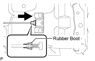
| 16. INSTALL NO. 4 PARKING BRAKE CABLE ASSEMBLY (for Automatic Transaxle) |
Install the No. 4 parking brake cable assembly to the parking brake equalizer.
 |
Slide the rubber boot back as shown in the illustration.
 |
| 17. CONNECT NO. 2 PARKING BRAKE CABLE ASSEMBLY (for Automatic Transaxle) |
Connect the No. 2 parking brake cable assembly to the parking brake equalizer.
 |
| 18. CONNECT NO. 3 PARKING BRAKE CABLE ASSEMBLY (for Automatic Transaxle) |
Connect the No. 3 parking brake cable assembly to the parking brake equalizer.
 |
| 19. INSTALL CROSS MEMBER FLOOR NO. 4 REINFORCEMENT SUB-ASSEMBLY (for Automatic Transaxle) |
Install the cross member floor No. 4 reinforcement sub-assembly with the 8 bolts.
 |
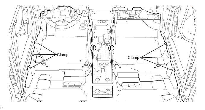
| 20. INSTALL FRONT FLOOR CARPET ASSEMBLY (for Automatic Transaxle) |
Engage the 6 clamps and the 2 claws and install the front floor carpet assembly.
| 21. INSTALL LUGGAGE DOOR LOCK OPEN LEVER SUB-ASSEMBLY (for Automatic Transaxle) |
Engage the claw and install the luggage door open lever sub-assembly with the screw.
 |
| 22. INSTALL FRONT FLOOR CAUTION PLATE COVER (for Automatic Transaxle) |
Engage the claw and the clip and install the front floor caution plate cover.
 |
| 23. INSTALL LOWER CENTER PILLAR GARNISH LH (for Automatic Transaxle) |
Engage the 2 claws and 2 clips, then install the lower center pillar garnish LH.
 |
| 24. INSTALL REAR DOOR OPENING TRIM WEATHERSTRIP LH (for Automatic Transaxle) |
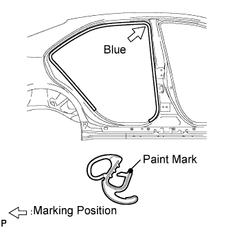
Install the rear door opening trim weatherstrip LH as shown in the illustration.
- NOTICE:
- After installation, check that the corners fit correctly.
 |
| 25. INSTALL REAR DOOR SCUFF PLATE LH (for Automatic Transaxle) |
Engage the 5 claws and 2 clips, then install the rear door scuff plate LH.
 |
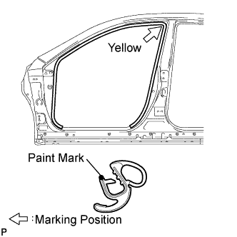
| 26. INSTALL FRONT DOOR OPENING TRIM WEATHERSTRIP LH (for Automatic Transaxle) |
Install the front door opening trim weatherstrip LH as shown in the illustration.
- NOTICE:
- After installation, check that the corners fit correctly.
 |
| 27. INSTALL LOWER CENTER PILLAR GARNISH RH (for Automatic Transaxle) |
- HINT:
- Use the same procedures for the RH side and the LH side.
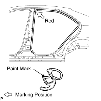
| 28. INSTALL REAR DOOR OPENING TRIM WEATHERSTRIP RH (for Automatic Transaxle) |
Install the rear door opening trim weatherstrip RH as shown in the illustration.
- NOTICE:
- After installation, check that the corners fit correctly.
 |
| 29. INSTALL REAR DOOR SCUFF PLATE RH (for Automatic Transaxle) |
- HINT:
- Use the same procedures for the RH side and the LH side.
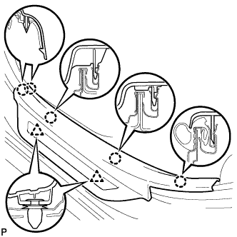
| 30. INSTALL FRONT DOOR OPENING TRIM WEATHERSTRIP RH (for Automatic Transaxle) |
Install the front door opening trim weatherstrip RH as shown in the illustration.
- NOTICE:
- After installation, check that the corners fit correctly.
 |
| 31. INSTALL NO. 1 PARKING BRAKE CABLE ASSEMBLY (for Automatic Transaxle) |
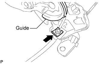
Pass the No. 1 parking brake cable assembly through the pedal guide.
 |
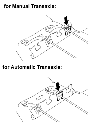
Using a brass bar and a hammer, install the clip to the No. 1 parking brake cable assembly.
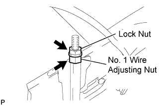
Temporarily tighten the lock nut and the No. 1 wire adjusting nut.
- NOTICE:
- Fully tighten the lock nut and the No. 1 wire adjusting nut when adjusting the parking brake pedal travel.
- Torque:
- 5.4 N*m{55 kgf*cm, 48 in.*lbf}
 |
Bend the parking brake pedal claw.
 |
| 32. INSTALL NO. 1 PARKING BRAKE CABLE ASSEMBLY (for Manual Transaxle) |
Pass the No. 1 parking brake cable assembly through the parking brake lever sub-assembly.
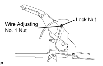
Temporarily tighten the lock nut and the No. 1 wire adjusting nut.
- NOTICE:
- Fully tighten the lock nut when adjusting the parking brake lever travel.
- Torque:
- 5.0 N*m{51 kgf*cm, 44 in.*lbf}
 |
Bend the parking brake lever claw.
 |
| 33. INSTALL PARKING BRAKE PEDAL ASSEMBLY (for Automatic Transaxle) |
- HINT:
- Refer to the procedures up to "INSTALL PARKING BRAKE PEDAL". (Link)
| 34. INSTALL PARKING BRAKE LEVER SUB-ASSEMBLY (for Manual Transaxle) |
- HINT:
- Refer to the procedures up to "INSTALL PARKING BRAKE LEVER". (CAMRY_ACV40 RM0000022KL001X.html)
| 35. INSTALL FRONT SEAT ASSEMBLY LH (for Manual Seat) |
- HINT:
- Refer to the procedures up to "INSTALL FRONT SEAT ASSEMBLY (for Manual Seat)". (CAMRY_ACV40 RM000001OH3004X.html)
| 36. INSTALL FRONT SEAT ASSEMBLY RH (for Manual Seat) |
- HINT:
- Use the same procedures for the RH side and the LH side.
| 37. INSTALL FRONT SEAT ASSEMBLY LH (for Power Seat) |
- HINT:
- Refer to the procedures up to "INSTALL FRONT SEAT ASSEMBLY (for Power Seat)". (CAMRY_ACV40 RM000000VBE009X.html)
| 38. INSTALL FRONT SEAT ASSEMBLY RH (for Power Seat) |
- HINT:
- Use the same procedures for the RH side and the LH side.
| 39. INSPECT PARKING BRAKE PEDAL TRAVEL (for Automatic Transaxle) |
Fully depress the parking brake pedal and release it to engage the parking brake.
Depress the pedal to the floor again, and release it to disengage the parking brake.
Slowly depress the parking brake pedal to the floor, and count the number of clicks.
- Parking brake pedal travel:
- 7 to 10 notches at 300 N (31 kgf, 67 lbf)
 |
| 40. INSPECT PARKING BRAKE LEVER TRAVEL (for Manual Transaxle) |
Pull the parking brake lever firmly.
Release the parking brake lock, and return the parking brake lever to its off position.
Slowly pull the parking brake lever all the way up, and count the number of clicks.
- Parking brake lever travel:
- 7 to 9 notches at 200 N (20 kgf, 45 lbf)
 |
| 41. ADJUST PARKING BRAKE PEDAL TRAVEL (for Automatic Transaxle) |
Depress the parking brake pedal. Hold the No. 1 wire adjusting nut using a wrench and loosen the lock nut.
 |
Release the parking brake pedal.
Turn the No. 1 wire adjusting nut until the parking brake pedal travel meets the above specification.
Hold the No. 1 wire adjusting nut using a wrench or an equivalent tool and tighten the lock nut.
- Torque:
- 5.4 N*m{55 kgf*cm, 48 in.*lbf}
Count the number of clicks after depressing and releasing the parking brake pedal 3 or 4 times.
Check whether the parking brake drags.
When operating the parking brake pedal, check that the parking brake indicator light comes on.
| 42. ADJUST PARKING BRAKE LEVER TRAVEL (for Manual Transaxle) |
Pull up the parking brake lever. Hold the No. 1 wire adjusting nut using a wrench and loosen the lock nut.
 |
Release the parking brake lever.
Turn the No. 1 wire adjusting nut until the parking brake lever travel meets the above specification.
Hold the No. 1 wire adjusting nut using a wrench or an equivalent tool and tighten the lock nut.
- Torque:
- 5.0 N*m{51 kgf*cm, 44 in.*lbf}
Count the number of clicks after depressing and releasing the parking brake lever 3 or 4 times.
Check whether the parking brake drags.
When operating the parking brake lever, check that the parking brake indicator light comes on.
| 43. CHECK FOR EXHAUST GAS LEAKS |