Radio Antenna Cord Installation
INSTALL ANTENNA CORD SUB-ASSEMBLY
INSTALL ROOF HEADLINING ASSEMBLY
INSTALL NO. 2 ANTENNA CORD SUB-ASSEMBLY (for LHD)
INSTALL NO. 2 ANTENNA CORD SUB-ASSEMBLY (for RHD)
INSTALL NO. 2 HEATER TO REGISTER DUCT
INSTALL NO. 3 HEATER TO REGISTER DUCT
INSTALL NO. 1 HEATER TO REGISTER DUCT
INSTALL DEFROSTER NOZZLE ASSEMBLY
INSTALL SIDE NO. 2 DEFROSTER NOZZLE DUCT
INSTALL SIDE NO. 1 DEFROSTER NOZZLE DUCT
INSTALL INSTRUMENT PANEL SAFETY PAD ASSEMBLY
Radio Antenna Cord -- Installation |
| 1. INSTALL ANTENNA CORD SUB-ASSEMBLY |
- HINT:
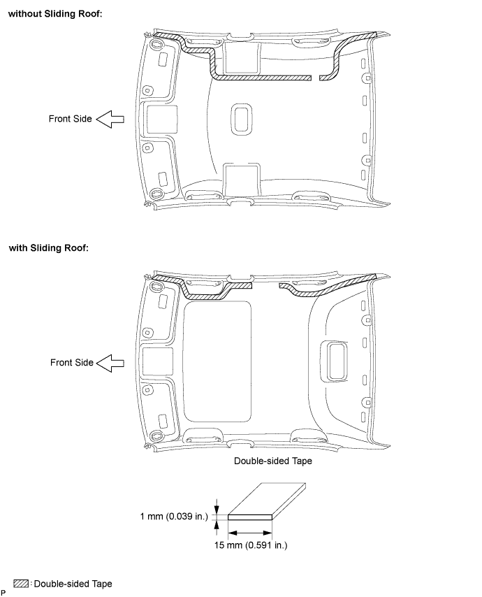
- The double-sided tape and tape are not available as supply parts. If these tapes still have enough adhesion to secure the roof headlining and antenna cord, reuse the tapes. If the roof headlining has been replaced with a new one, or if the tape and/or the double-sided tape is no longer sticky, apply new tape following the procedures below.
Apply new double-sided tape.
Remove the double-sided tape from the roof headlining assembly.
Peel off the appropriate amount of new double-sided tape. Be careful not to touch the adhesive surface.
Apply the double-sided tape to the roof headlining while aligning the tape with the markings on the roof headlining assembly.
Peel off the backing sheet from the double-sided tape.
Install the antenna cord to the roof headlining assembly from the front of the vehicle.
Put the strips of the tape back to the positions shown in the illustration in order to secure the antenna cord to the roof headlining assembly.
- HINT:
- If the tape is no longer sticky, use other tape, such as packing tape, that has enough adhesion to secure the antenna cord to the roof headlining assembly.
- For the right front corner of the roof headlining assembly, align the marking tape on the antenna cord with the protrusion of the roof headlining, and wrap tape around the antenna cord and roof headlining assembly once or twice to securely hold them.
- For the right rear corner of the roof headlining assembly, align the marking tape on the antenna cord with the rear edge of the roof headlining, and secure the antenna cord to the roof headlining assembly with tape.
- For the part of the antenna cord near the center of the roof headlining assembly, position the marking tape on the antenna cord within the area indicated by the marking line. Secure the antenna cord to the roof headlining assembly with tape as shown in the illustration. (without sliding roof)
| 2. INSTALL ROOF HEADLINING ASSEMBLY |
- HINT:
- Refer to the procedure from Install Roof Headlining Assembly (Link).
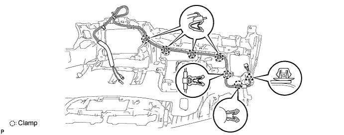
| 3. INSTALL NO. 2 ANTENNA CORD SUB-ASSEMBLY (for LHD) |
Engage the 6 clamps and clip and install the No. 2 antenna cord sub-assembly.
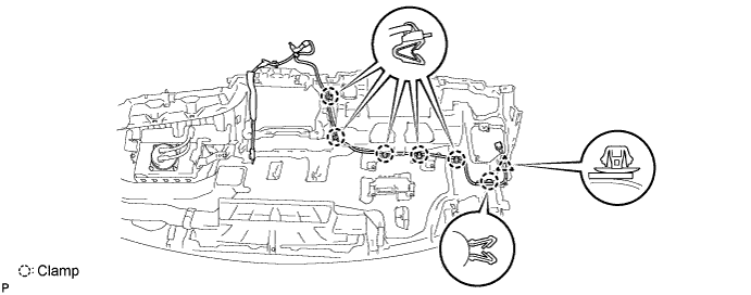
| 4. INSTALL NO. 2 ANTENNA CORD SUB-ASSEMBLY (for RHD) |
Engage the 6 clamps and clip and install the No. 2 antenna cord sub-assembly.
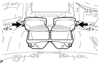
| 5. INSTALL NO. 2 HEATER TO REGISTER DUCT |
Install the No. 2 heater to register duct with the 2 screws <F>.
| 6. INSTALL NO. 3 HEATER TO REGISTER DUCT |
Install the No. 3 heater to register duct with the 3 screws <F>.
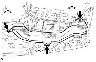
| 7. INSTALL NO. 1 HEATER TO REGISTER DUCT |
Install the No. 1 heater to register duct with the 3 screws <F>.
| 8. INSTALL DEFROSTER NOZZLE ASSEMBLY |
Install the defroster nozzle assembly with the 3 screws <F>.
| 9. INSTALL SIDE NO. 2 DEFROSTER NOZZLE DUCT |
Install the side No. 2 defroster nozzle duct with the screw <F>.
| 10. INSTALL SIDE NO. 1 DEFROSTER NOZZLE DUCT |
Install the side No. 1 defroster nozzle duct with the screw <F>.
| 11. INSTALL INSTRUMENT PANEL SAFETY PAD ASSEMBLY |
- HINT:
- Refer to the procedure from Install Instrument Panel Safety Pad Assembly (CAMRY_ACV40 RM0000024DA07FX.html).