REMOVE SHIFT LEVER KNOB SUB-ASSEMBLY (for Automatic Transaxle)
REMOVE FLOOR SHIFT POSITION INDICATOR HOUSING SUB-ASSEMBLY (for Automatic Transaxle)
REMOVE UPPER CONSOLE REAR PANEL SUB-ASSEMBLY (for Automatic Transaxle)
REMOVE UPPER CONSOLE REAR PANEL SUB-ASSEMBLY (for Manual Transaxle)
REMOVE REAR POWER OUTLET SOCKET ASSEMBLY (for Automatic Transaxle)
Power Outlet Socket -- Removal |
| 1. REMOVE SHIFT LEVER KNOB SUB-ASSEMBLY (for Automatic Transaxle) |
Turn the shift lever knob counterclockwise and remove the shift lever knob sub-assembly.
 |
| 2. REMOVE SHIFT LEVER KNOB SUB-ASSEMBLY (for Manual Transaxle) |
Turn the shift lever knob counterclockwise and remove the shift lever knob sub-assembly.
 |
| 3. REMOVE NO. 1 INSTRUMENT CLUSTER FINISH PANEL GARNISH |
Disengage the 2 clips and remove the No. 1 instrument cluster finish panel garnish.
 |
| 4. REMOVE NO. 2 INSTRUMENT CLUSTER FINISH PANEL GARNISH |
Disengage the 2 clips and remove the No. 2 instrument cluster finish panel garnish.
 |
| 5. REMOVE FLOOR SHIFT POSITION INDICATOR HOUSING SUB-ASSEMBLY (for Automatic Transaxle) |
Disengage the 6 claws and the 3 clips, and then remove the floor shift position indicator housing sub-assembly.
 |
with Seat Heater System:
Disconnect each connector.
| 6. REMOVE UPPER CONSOLE PANEL (for Manual Transaxle) |
Open the lid of the upper console panel.
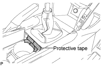 |
Apply protective tape to the area shown in the illustration.
Using a moulding remover, disengage the 2 claws and the 5 clips, and then remove the upper console panel as shown in the illustration.
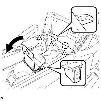 |
with Seat Heater System:
Disconnect each connector.
| 7. REMOVE UPPER CONSOLE REAR PANEL SUB-ASSEMBLY (for Automatic Transaxle) |
Disengage the 3 claws and the 5 clips.
 |
Disconnect the connector and remove the upper console rear panel sub-assembly.
| 8. REMOVE UPPER CONSOLE REAR PANEL SUB-ASSEMBLY (for Manual Transaxle) |
Disengage the 3 claws and the 5 clips, and remove the upper console rear panel sub-assembly.
 |
| 9. REMOVE UPPER CONSOLE PANEL SUB-ASSEMBLY |
Remove the 2 screws <F>.
 |
Disengage the 4 claws.
Disconnect each connector and remove the upper console panel sub-assembly.
- HINT:
- Set the shift lever in the D position.
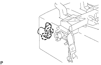
| 10. REMOVE FRONT POWER OUTLET SOCKET ASSEMBLY |
Disengage the claw and remove the front power outlet socket assembly as shown in the illustration.
 |
| 11. REMOVE FRONT POWER OUTLET SOCKET COVER |
Disengage the 2 claws and remove the front power outlet socket cover.
 |
| 12. REMOVE REAR POWER OUTLET SOCKET ASSEMBLY (for Automatic Transaxle) |
Disengage the claw and remove the rear power outlet socket assembly.
 |