Dtc B1242 Wireless Door Lock Tuner Circuit Malfunction
DESCRIPTION
WIRING DIAGRAM
INSPECTION PROCEDURE
CHECK HARNESS AND CONNECTOR (CERTIFICATION ECU - DOOR CONTROL RECEIVER)
INSPECT CERTIFICATION ECU (SMART KEY ECU ASSEMBLY)
DTC B1242 Wireless Door Lock Tuner Circuit Malfunction |
DESCRIPTION
- The electrical key antenna is used to receive electric waves relating to the entry functions of the entry and start system. The certification ECU (smart key ECU assembly) decodes the requested entry and start system operation by identifying a key code based on electric waves received via the electrical key antenna and the door control receiver.
- The door control receiver receives a signal from the wireless door control transmitter and sends signals to the main body ECU through the certification ECU (smart key ECU assembly).
- The certification ECU (smart key ECU assembly) then sends a command, according to the requested operation, to each ECU. (e.g. If door lock operation is requested, the ECU sends a door lock command to the main body ECU.)
DTC No.
| DTC Detection Condition
| Trouble Area
|
B1242
| The certification ECU (smart key ECU assembly) detects that there is a short in the circuit between terminals RSSI, or between terminals DATA and RDA.
| - Door Control Receiver
- Wire harness or connector
- Certification ECU (Smart key ECU assembly)
|
WIRING DIAGRAM
INSPECTION PROCEDURE
| 1.CHECK HARNESS AND CONNECTOR (CERTIFICATION ECU - DOOR CONTROL RECEIVER) |
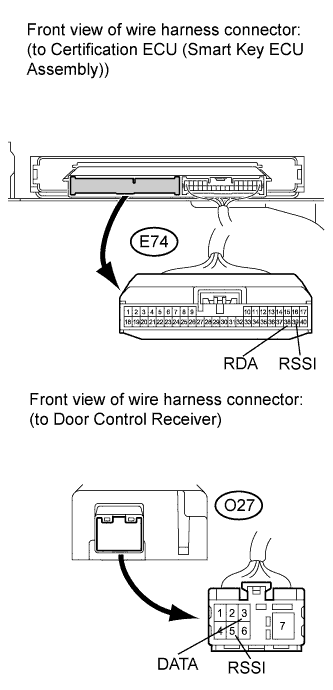
Disconnect the E74 certification ECU (smart key ECU assembly) connector and O27 door control receiver connector.
Measure the resistance according to the value(s) in the table below.
- Standard Resistance:
Tester Connection
| Condition
| Specified Condition
|
E74-39 (RSSI) - O27-5 (RSSI)
| Always
| Below 1 Ω
|
E74-38 (RDA) - O27-3 (DATA)
| Always
| Below 1 Ω
|
E74-39 (RSSI) - E74-38 (RDA)
| Always
| 10 kΩ or higher
|
E74-39 (RSSI) - Body ground
| Always
| 10 kΩ or higher
|
E74-38 (RDA) - Body ground
| Always
| 10 kΩ or higher
|
| | REPAIR OR REPLACE HARNESS OR CONNECTOR |
|
|
| 2.INSPECT CERTIFICATION ECU (SMART KEY ECU ASSEMBLY) |
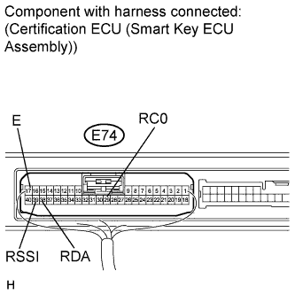
Reconnect the E74 ECU connector.
Measure the voltage and check for pulse according to the value(s) in the table below.
- Standard:
Tester Connection
| Condition
| Specified Condition
|
E74-29 (RC0) - E74-17 (E)
| Engine switch off, all doors closed and transmitter switch not pressed
| Pulse generation
|
Engine switch off, all doors closed and transmitter switch pressed
| 4.6 to 5.4 V
|
| | REPLACE CERTIFICATION ECU (SMART KEY ECU ASSEMBLY) |
|
|