Power Steering Link Installation
INSTALL POWER STEERING RACK HOUSING HEAT INSULATOR (for 2GR-FE LHD)
INSTALL POWER STEERING RACK HOUSING HEAT INSULATOR (for 2GR-FE RHD)
INSTALL POWER STEERING LINK ASSEMBLY
CONNECT PRESSURE FEED TUBE ASSEMBLY (for LHD)
CONNECT PRESSURE FEED TUBE ASSEMBLY (for 2AZ-FE RHD)
INSTALL RETURN TUBE ASSEMBLY (for 2AZ-FE RHD)
CONNECT STEERING GEAR OUTLET RETURN TUBE (for 2AZ-FE RHD)
CONNECT PRESSURE FEED TUBE ASSEMBLY (for 2GR-FE RHD)
INSTALL RETURN TUBE ASSEMBLY (for 2GR-FE RHD)
CONNECT STEERING GEAR OUTLET RETURN TUBE (for 2GR-FE RHD)
INSTALL ENGINE ASSEMBLY WITH TRANSAXLE
CONNECT TIE ROD ASSEMBLY LH
CONNECT TIE ROD ASSEMBLY RH
CONNECT STEERING SLIDING YOKE
INSTALL FRONT WHEELS
CONNECT CABLE TO NEGATIVE BATTERY TERMINAL
BLEED POWER STEERING FLUID
CHECK POWER STEERING FLUID LEVEL
CHECK FOR POWER STEERING FLUID LEAKAGE
CHECK FOR EXHAUST GAS LEAKS
PLACE FRONT WHEELS FACING STRAIGHT AHEAD
INSPECT AND ADJUST FRONT WHEEL ALIGNMENT
Power Steering Link -- Installation |
| 1. INSTALL POWER STEERING RACK HOUSING HEAT INSULATOR (for 2GR-FE LHD) |
Install the power steering rack housing heat insulator to the power steering link assembly.
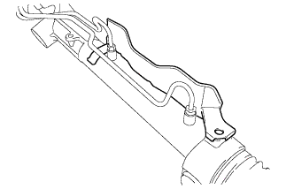
| 2. INSTALL POWER STEERING RACK HOUSING HEAT INSULATOR (for 2GR-FE RHD) |
Install the power steering rack housing heat insulator to the power steering link assembly with the bolt.
- Torque:
- 9.8 N*m{100 kgf*cm, 87 in.*lbf}
| 3. INSTALL POWER STEERING LINK ASSEMBLY |
Install the power steering link assembly with the 2 bolts and 2 nuts.
- Torque:
- 70 N*m{714 kgf*cm, 52 ft.*lbf}
| 4. CONNECT PRESSURE FEED TUBE ASSEMBLY (for LHD) |
Temporarily connect the pressure feed tube assembly to the power steering link assembly.
Install the pressure feed tube assembly clamp with the 2 bolts.
- Torque:
- 9.8 N*m{100 kgf*cm, 87 in.*lbf}
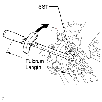
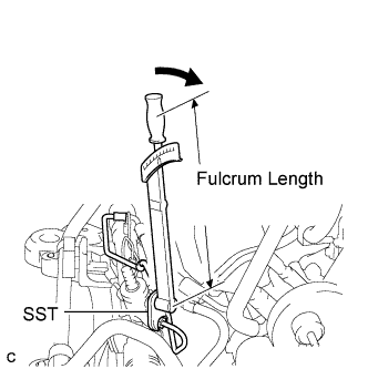
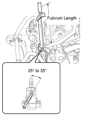
Using SST, tighten the pressure feed tube assembly (pressure feed tube side).
- SST
- 09023-12701
- Torque:
- Without SST:
- 25 N*m{250 kgf*cm, 18 ft.*lbf}
- With SST:
- 22 N*m{227 kgf*cm, 16 ft.*lbf}
- NOTICE:
- Use a torque wrench with a fulcrum length of 300 mm (11.81 in.).
- This torque value is effective when SST is parallel to the torque wrench.
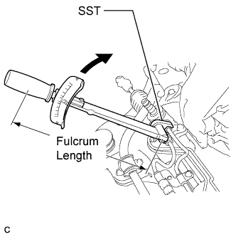
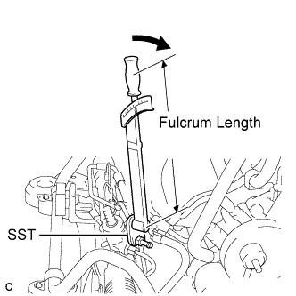
Using SST, tighten the pressure feed tube assembly (return tube side).
- SST
- 09023-12701
- Torque:
- Without SST:
- 25 N*m{250 kgf*cm, 18 ft.*lbf}
- With SST:
- 22 N*m{227 kgf*cm, 16 ft.*lbf}
- NOTICE:
- Use a torque wrench with a fulcrum length of 300 mm (11.81 in.).
- This torque value is effective when SST is parallel to the torque wrench.
| 5. CONNECT PRESSURE FEED TUBE ASSEMBLY (for 2AZ-FE RHD) |
Install the pressure feed tube assembly clamp with the bolt.
- Torque:
- 9.8 N*m{100 kgf*cm, 87 in.*lbf}
Using SST, connect the pressure feed tube assembly to the power steering link assembly.
- SST
- 09023-12701
- Torque:
- Without SST:
- 25 N*m{250 kgf*cm, 18 ft.*lbf}
- With SST:
- 22 N*m{227 kgf*cm, 16 ft.*lbf}
- NOTICE:
- Use a torque wrench with a fulcrum length of 300 mm (11.81 in.).
- This torque value is effective when SST is parallel to the torque wrench.
| 6. INSTALL RETURN TUBE ASSEMBLY (for 2AZ-FE RHD) |
Using SST, install the return tube assembly to the power steering link assembly.
- SST
- 09023-12701
- Torque:
- Without SST:
- 25 N*m{250 kgf*cm, 18 ft.*lbf}
- With SST:
- 22 N*m{227 kgf*cm, 16 ft.*lbf}
- NOTICE:
- Use a torque wrench with a fulcrum length of 300 mm (11.81 in.).
- This torque value is effective when SST is parallel to the torque wrench.
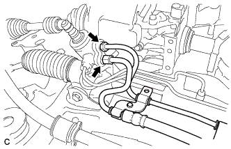
| 7. CONNECT STEERING GEAR OUTLET RETURN TUBE (for 2AZ-FE RHD) |
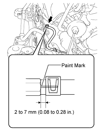
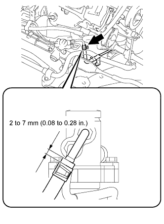
Connect the steering gear outlet return tube to the return tube assembly with the clip.
- NOTICE:
- Connect the steering gear outlet return tube with the paint mark facing upward.
- Push the steering gear outlet return tube as far as it will go as shown in the illustration.
- Install the clip at the position specified in the illustration.
| 8. CONNECT PRESSURE FEED TUBE ASSEMBLY (for 2GR-FE RHD) |
Install the pressure feed tube assembly clamp with the bolt.
- Torque:
- 9.8 N*m{100 kgf*cm, 87 in.*lbf}
Using SST, connect the pressure feed tube assembly to the power steering link assembly.
- SST
- 09023-12701
- Torque:
- Without SST:
- 25 N*m{250 kgf*cm, 18 ft.*lbf}
- With SST:
- 22 N*m{227 kgf*cm, 16 ft.*lbf}
- NOTICE:
- Use a torque wrench with a fulcrum length of 300 mm (11.81 in.).
- This torque value is effective when SST is parallel to the torque wrench.
| 9. INSTALL RETURN TUBE ASSEMBLY (for 2GR-FE RHD) |
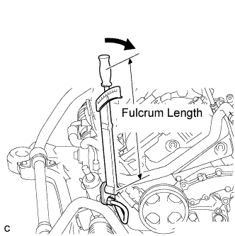
Using SST, install the return tube assembly to the power steering link assembly.
- SST
- 09023-12701
- Torque:
- Without SST:
- 25 N*m{250 kgf*cm, 18 ft.*lbf}
- With SST:
- 22 N*m{227 kgf*cm, 16 ft.*lbf}
- NOTICE:
- Install the return tube assembly at the angle specified in the illustration.
- NOTICE:
- Use a torque wrench with a fulcrum length of 300 mm (11.81 in.).
- This torque value is effective when SST is parallel to the torque wrench.
| 10. CONNECT STEERING GEAR OUTLET RETURN TUBE (for 2GR-FE RHD) |
Connect the steering gear outlet return tube to the return tube assembly with the clip.
- NOTICE:
- Push the steering gear outlet return tube as far as it will go as shown in the illustration.
- Install the clip at the position specified in the illustration.
| 11. INSTALL ENGINE ASSEMBLY WITH TRANSAXLE |
- HINT:
- Refer to the instructions for installation of the engine assembly (CAMRY_ACV40 RM000000YIK00WX.html for 2GR-FE).
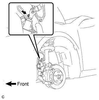
| 12. CONNECT TIE ROD ASSEMBLY LH |
Connect the tie rod assembly LH to the steering knuckle with the nut.
- Torque:
- 49 N*m{500 kgf*cm, 36 ft.*lbf}
Install a new cotter pin.
- NOTICE:
- Further tighten the nut up to 60° if the holes for the cotter pin are not aligned.
| 13. CONNECT TIE ROD ASSEMBLY RH |
- HINT:
- Perform the same procedure as for the LH side.
| 14. CONNECT STEERING SLIDING YOKE |
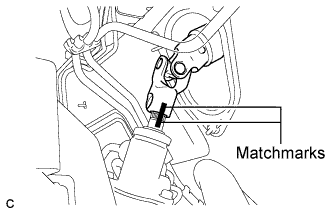
Align the matchmarks on the steering sliding yoke and the steering link assembly.
Install the bolt.
- Torque:
- 35 N*m{360 kgf*cm, 26 ft.*lbf}
- Torque:
- 103 N*m{1,050 kgf*cm, 76 ft.*lbf}
| 16. CONNECT CABLE TO NEGATIVE BATTERY TERMINAL |
| 17. BLEED POWER STEERING FLUID |
Check the fluid level (CAMRY_ACV40 RM000001A0S010X_01_0006.html).
Jack up the front of the vehicle and support it with stands.
Turn the steering wheel.
With the engine stopped, turn the steering wheel slowly from lock to lock several times.
Lower the vehicle.
Start the engine.
Run the engine at idle for a few minutes.
Turn the steering wheel.
With the engine idling, turn the steering wheel left or right to the full lock position and keep it in that position for 2 to 3 seconds, then turn the steering wheel to the opposite full lock position and keep it there for 2 to 3 seconds.
Repeat this procedure several times.
Stop the engine.
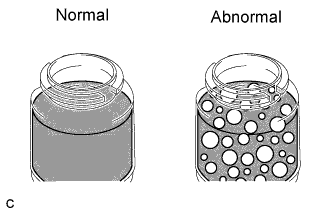
Check for foaming or emulsification.
- HINT:
- If the system has to be bled twice because of forming or emulsification, be sure to check for fluid leaks in the system.
Check the fluid level (CAMRY_ACV40 RM000001A0S010X_01_0006.html).
| 18. CHECK POWER STEERING FLUID LEVEL |
Keep the vehicle level.
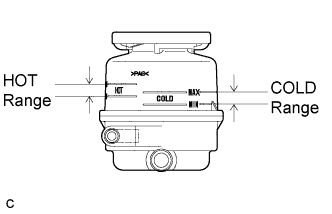
With the engine stopped, check the fluid level in the fluid reservoir.
If necessary, add fluid.
- Fluid:
- ATF DEXRON II or III, or equivalent
- HINT:
- If the fluid is hot, check that the fluid level is within the HOT range on the fluid reservoir. If the fluid is cold, check that the fluid level is within the COLD range.
Start the engine and run it at idle.
Turn the steering wheel from lock to lock several times to raise fluid temperature.
- Fluid temperature:
- 75°C (167°F) to 80°C (176°F)
Check for foaming or emulsification.
If foaming or emulsification is identified, bleed the power steering system (CAMRY_ACV40 RM000001BOQ011X_01_0001.html).
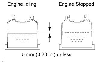
With the engine idling, measure the fluid level in the fluid reservoir.
Stop the engine.
Wait a few minutes and remeasure the fluid level in the fluid reservoir.
- Maximum fluid level rise:
- 5 mm (0.20 in.)
If a problem is found, bleed the power steering system (CAMRY_ACV40 RM000001BOQ011X_01_0001.html).
Check the fluid level.
| 19. CHECK FOR POWER STEERING FLUID LEAKAGE |
| 20. CHECK FOR EXHAUST GAS LEAKS |
| 21. PLACE FRONT WHEELS FACING STRAIGHT AHEAD |
| 22. INSPECT AND ADJUST FRONT WHEEL ALIGNMENT |
- HINT:
- (CAMRY_ACV40 RM0000011DA015X.html)