Oil Pump -- Installation |
| 1. INSTALL OIL PUMP ASSEMBLY |
Install a new gasket and the oil pump with the 3 bolts.
- Torque:
- 19 N*m{194 kgf*cm, 14 ft.*lbf}
 |
| 2. INSTALL NO. 2 CHAIN SUB-ASSEMBLY |
Set the crankshaft key into the left horizontal position.
 |
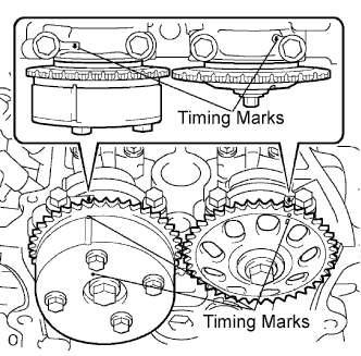
Turn the drive shaft so that the cutout faces upward.
Align the yellow mark links with the timing marks of each gear as shown in the illustration.
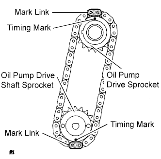 |
Install the sprockets onto the crankshaft and oil pump shaft with the chain wrapped on the gears.
Temporarily tighten the oil pump drive shaft sprocket with the nut.
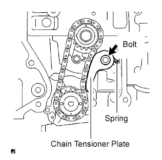
Insert the damper spring into the adjusting hole, and then install the chain tensioner plate with the bolt.
- Torque:
- 12 N*m{122 kgf*cm, 9 ft.*lbf}
 |
Align the adjusting hole of the oil pump drive shaft sprocket with the groove of the oil pump.
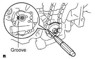 |
Insert a 4 mm diameter bar into the adjusting hole of the oil pump drive shaft gear to lock the gear in position, and then tighten the nut.
- Torque:
- 30 N*m{301 kgf*cm, 22 ft.*lbf}
Rotate the crankshaft clockwise by 90°, and align the crankshaft key to the top.
 |
| 3. INSTALL CRANKSHAFT TIMING SPROCKET |
Install the crankshaft timing sprocket.
 |
| 4. INSTALL NO. 1 CHAIN VIBRATION DAMPER |
Install the chain vibration damper with the 2 bolts.
- Torque:
- 9.0 N*m{92 kgf*cm, 80 in.*lbf}
 |
| 5. INSTALL CHAIN SUB-ASSEMBLY |
Set the No. 1 cylinder to TDC/compression.
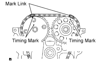
Turn the camshafts with a wrench (using the hexagonal lobe) to align the timing marks of the camshaft timing gear with each timing mark located on the No. 1 and No. 2 bearing caps as shown in the illustration.
Using the crankshaft pulley bolt, turn the crankshaft to position with the key on the crankshaft upward.

 |
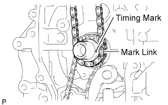
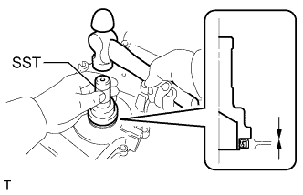
Install the chain onto the crankshaft timing sprocket with the gold or pink mark link aligned with the timing mark on the crankshaft.
 |
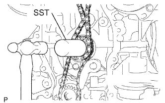
Using SST and a hammer, tap in the crankshaft timing sprocket.
- SST
- 09309-37010
 |
Align the gold or yellow link with each timing mark located on the camshaft timing gear and sprocket, then install the chain.
 |
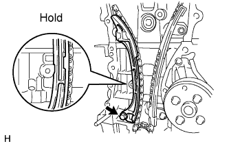
| 6. INSTALL CHAIN TENSIONER SLIPPER |
Install the chain tensioner slipper with the bolt.
- Torque:
- 19 N*m{194 kgf*cm, 14 ft.*lbf}
 |
| 7. INSTALL TIMING CHAIN GUIDE |
Install the timing chain guide with the bolt.
- Torque:
- 9.0 N*m{92 kgf*cm, 80 in.*lbf}
 |
| 8. INSTALL NO. 1 CRANKSHAFT POSITION SENSOR PLATE |
Install the sensor plate with the "F" mark facing forward.
 |
| 9. INSTALL TIMING CHAIN CASE OIL SEAL |
Using SST, tap in a new oil seal until its surface is flush with the timing chain cover edge.
- SST
- 09223-22010
 |
Apply a light coat of MP grease to the lip of the oil seal.
- NOTICE:
- Keep the gap between the timing chain cover edge and the oil seal free of foreign matter.
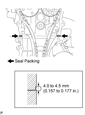
| 10. INSTALL TIMING CHAIN COVER SUB-ASSEMBLY |
Remove any old packing (FIPG) material and be careful not to drop any oil on the contact surfaces of the timing chain cover, cylinder head and cylinder block.
Apply seal packing (diameter: 4.0 to 4.5 mm (0.157 to 0.177 in.)) as shown in the illustration.
- Seal packing:
- Toyota Genuine Seal Packing Black, Three Bond 1207B or Equivalent
 |
Apply seal packing in a continuous bead as shown in the illustration.
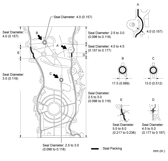
- Seal packing:
- Toyota Genuine Seal Packing Black, Three Bond 1207B or Equivalent
- NOTICE:
- Remove any oil from the contact surface.
- Install the chain cover within 3 minutes after applying seal packing.
- Do not start the engine for at least 2 hours after installing.
Install the timing chain cover with the 12 bolts and 2 nuts.
- Torque:
- Bolt A:
- 9.0 N*m{92 kgf*cm, 80 in.*lbf}
- Bolt B:
- 25 N*m{255 kgf*cm, 18 ft.*lbf}
- Bolt C:
- 55 N*m{561 kgf*cm, 41 ft.*lbf}
- Nut:
- 11 N*m{112 kgf*cm, 8 ft.*lbf}
Bolt length Item Length Bolt A 30 mm (1.18 in.) length for 10 mm head Bolt B 30 mm (1.18 in.) length for 12 mm head Bolt C 40 mm (1.57 in.) length for 14 mm head
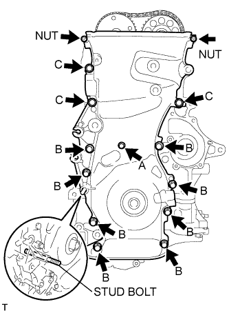 |
Using a E10 "torx" socket, install the stud bolt to the drive belt tensioner.
- Torque:
- 22 N*m{220 kgf*cm, 16 ft.*lbf}
| 11. INSTALL V-RIBBED BELT TENSIONER ASSEMBLY |
Install the V-ribbed belt tensioner with the bolt and nut.
- Torque:
- 60 N*m{607 kgf*cm, 44 ft.*lbf}
- NOTICE:
- Do not lift the engine more than necessary.
 |
| 12. INSTALL ENGINE MOUNTING BRACKET RH |
Install the engine mounting bracket with the 3 bolts.
- Torque:
- 54 N*m{551 kgf*cm, 40 ft.*lbf}
 |
| 13. INSTALL ENGINE MOUNTING INSULATOR |
Raise the engine and install the engine mounting insulator RH.
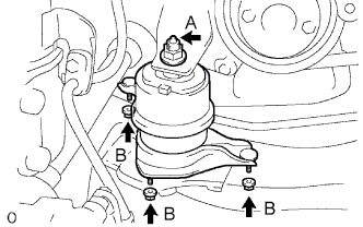 |
Install the engine mounting insulator RH with the 4 nuts.
- Torque:
- Nut A:
- 95 N*m{969 kgf*cm, 70 ft.*lbf}
- Nut B:
- 87 N*m{888 kgf*cm, 64 ft.*lbf}
Install the steering gear return tube clamps to the frame with the 2 bolts.
- Torque:
- 8.0 N*m{80 kgf*cm, 69 in.*lbf}
 |
Install the engine mounting insulator FR with the bolt.
- Torque:
- 87 N*m{888 kgf*cm, 64 ft.*lbf}
 |
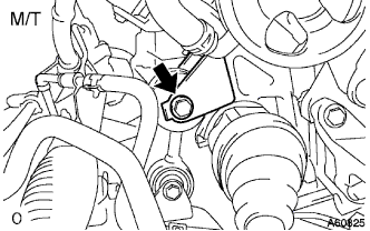
M/T:
Install the engine lateral control rod with the bolt.- Torque:
- 89 N*m{910 kgf*cm, 66 ft.*lbf}
 |
| 14. INSTALL OIL PAN SUB-ASSEMBLY |
Remove any old packing material and be careful not to drop any oil on the contact surfaces of the cylinder block and oil pan.
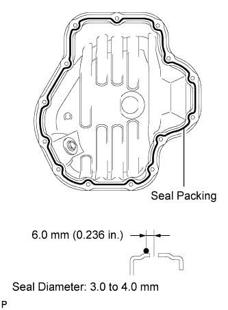 |
Apply a continuous bead of seal packing (Diameter 3.0 to 4.0 mm (0.118 to 0.157 in.)) as shown in the illustration.
- Seal packing:
- Toyota Genuine Seal Packing Block, Three Bond 1207B or Equivalent
- NOTICE:
- Remove any oil from the contact surfaces.
- Install the oil pan within 3 minutes after applying seal packing.
- Do not start the engine for at least 2 hours after installing.
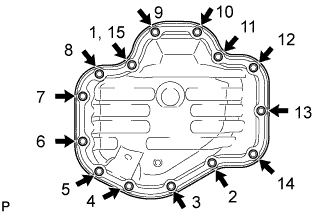
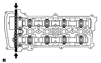
Install the oil pan to the cylinder block.
Uniformly tighten the 12 bolts and 2 nuts in the sequence shown in the illustration.
- Torque:
- 9.0 N*m{92 kgf*cm, 80 in.*lbf}
 |
| 15. INSTALL CRANK POSITION SENSOR |
Apply a light coat of engine oil to the O-ring on the crankshaft position sensor.
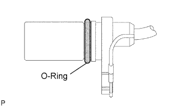 |
Install the crankshaft position sensor with the bolt.
- Torque:
- 9.0 N*m{92 kgf*cm, 80 in.*lbf}
 |
Connect the crankshaft position sensor connector.
| 16. INSTALL CRANKSHAFT PULLEY |
Align the pulley set key with the key groove of the pulley.
Using SST, fix the pulley in place and tighten the bolt.
- SST
- 09213-54015(91651-60855)
09330-00021
- Torque:
- 180 N*m{1,835 kgf*cm, 133 ft.*lbf}
 |
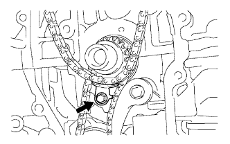
| 17. INSTALL NO. 1 CHAIN TENSIONER ASSEMBLY |
Release the ratchet pawl, then fully push in the plunger and hook the hook to the pin so that the plunger is in the position shown in the illustration.
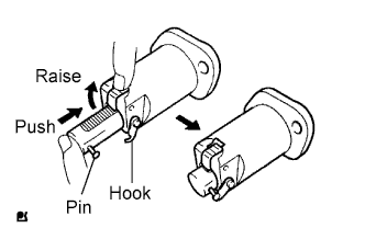 |
Install a new gasket and the chain tensioner with the 2 nuts.
- Torque:
- 9.0 N*m{92 kgf*cm, 80 in.*lbf}
- NOTICE:
- If the hook releases the plunger while the chain tensioner is being installed, set the hook again.
 |
Turn the crankshaft counterclockwise, then disconnect the plunger knock pin from the hook.
 |
Turn the crankshaft clockwise, then check that the plunger is extended.
 |
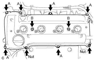
| 18. INSTALL CYLINDER HEAD COVER SUB-ASSEMBLY |
Remove any old packing material from the contact surface.
Apply seal packing to the 2 locations shown in the illustration.
- Seal packing:
- Toyota Genuine Seal Packing Block, Three Bond 1207B or Equivalent
- NOTICE:
- Remove any oil from the contact surface.
- Install the cylinder head cover within 3 minutes of applying seal packing.
- Do not add engine oil for at least 2 hours after installing the cylinder head cover.
 |
Install the cylinder head cover with the 8 bolts and 2 nuts.
- Torque:
- Bolt A:
- 11 N*m{112 kgf*cm, 8 ft.*lbf}
- Bolt B:
- 14 N*m{143 kgf*cm, 10 ft.*lbf}
- Nut:
- 11 N*m{112 kgf*cm, 8 ft.*lbf}
 |
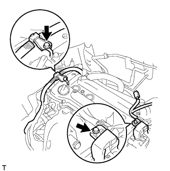
Install the 2 engine wires with the 2 bolts.
- Torque:
- 8.4 N*m{86 kgf*cm, 74 in.*lbf}
 |
| 19. INSTALL NO. 2 VENTILATION HOSE |
| 20. INSTALL VENTILATION HOSE |
| 21. INSTALL IGNITION COIL ASSEMBLY |
Install the 4 ignition coils with the 4 bolts.
- Torque:
- 9.0 N*m{92 kgf*cm, 80 in.*lbf}
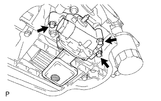
| 22. INSTALL VANE PUMP ASSEMBLY |
Install the vane pump to the engine with the 2 bolts.
- Torque:
- 43 N*m{439 kgf*cm, 32 ft.*lbf}
 |
Connect the oil pressure switch connector.
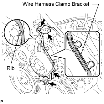
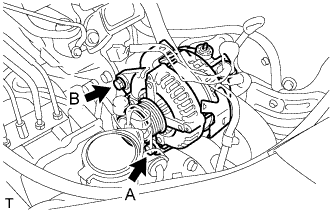
| 23. INSTALL GENERATOR ASSEMBLY |
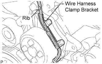
Confirm that the wire harness of the crankshaft position sensor is secured to the wire harness clamp bracket through the back of the rib of the timing chain cover.
 |
Install the generator assembly with the 2 bolts.
- Torque:
- Bolt A:
- 21 N*m{215 kgf*cm, 16 ft.*lbf}
- Bolt B:
- 52 N*m{530 kgf*cm, 38 ft.*lbf}
 |
Install the generator wire to terminal B with the nut.
- Torque:
- 9.8 N*m{100 kgf*cm, 87 in.*lbf}
 |
Install the clamp bracket with the bolt.
- Torque:
- 8.4 N*m{86 kgf*cm, 74 in.*lbf}
Attach the clamp and connect the generator connector to the generator.
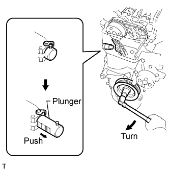
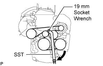
| 24. INSTALL V-RIBBED BELT |
Using SST and 19 mm socket wrench, loosen the V-ribbed belt tensioner arm clockwise, then install the V-ribbed belt.
- SST
- 09216-42010
- NOTICE:
- Be sure to connect SST and the tools so that they are in line during use.
- When retracting the tensioner, turn it clockwise slowly for 3 seconds or more. Do not apply force rapidly.
- After the tensioner is fully retracted, do not apply force any more than necessary.
 |
After installing the V-ribbed belt, check that it fits properly in the ribbed grooves. Check to confirm that the belt has not slipped out of the grooves on the bottom of the crank pulley by hand.
| 25. INSTALL NO. 2 ENGINE MOUNTING BRACKET RH |
Install the 3 bolts and No. 2 mounting bracket RH.
- Torque:
- 52 N*m{531 kgf*cm, 38 ft.*lbf}
 |
| 26. INSTALL ENGINE MOVING CONTROL ROD SUB-ASSEMBLY |
Install the engine moving control rod with the 3 bolts.
- Torque:
- 64 N*m{653 kgf*cm, 47 ft.*lbf}
 |
Install the ground cable with the bolt.
- Torque:
- 8.4 N*m{85 kgf*cm, 74 in.*lbf}
 |
| 27. INSTALL NO. 2 ENGINE MOUNTING STAY RH |
Install the No. 2 mounting stay RH with the 2 bolts.
- Torque:
- 64 N*m{653 kgf*cm, 47 ft.*lbf}
 |
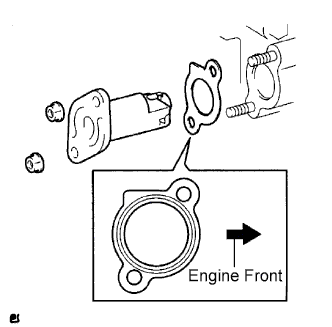
| 28. INSTALL FRONT EXHAUST PIPE ASSEMBLY |
| 29. ADD ENGINE OIL |
| 30. CONNECT CABLE TO NEGATIVE BATTERY TERMINAL |
- Torque:
- 6.9 N*m{70 kgf*cm, 61 in.*lbf}
| 31. CHECK ENGINE OIL LEAKS |
| 32. CHECK CHECK EXHAUST GAS LEAKS |
| 33. CHECK IGNITION TIMING |
Warm up the engine.
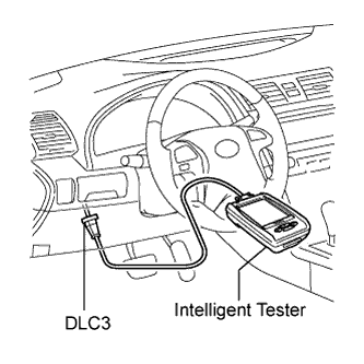
When using the intelligent tester:
Check the ignition timing.Connect the intelligent tester to the DLC3.
Enter DATA LIST MODE on the intelligent tester.
- Ignition timing:
- 8 to 12° BTDC at idle
- HINT:
- Refer to the intelligent tester operator's manual for help when selecting the DATA LIST.
 |
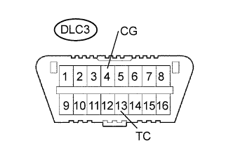
When not using the intelligent tester:
Check the ignition timing.Using SST, connect terminals 13 (TC) and 4 (CG) of the DLC3.
- SST
- 09843-18040
- NOTICE:
- Confirm the terminal numbers before connecting them. Connection with a wrong terminal can damage the engine.
- Turn off all electrical systems before connecting the terminals.
- Perform this inspection after the cooling fan motor is turned off.
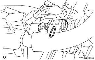
Remove the No. 1 engine cover.
Pull out the wire harness as shown in the illustration. Connect the clip of the timing light to the wire harness.
- NOTICE:
- Use a timing light which can detect the first signal.
- After checking, be sure to tape the wire harness.
Check the ignition timing at idle.
- Ignition timing:
- 8 to 12° BTDC at idle
- NOTICE:
- When checking the ignition timing, the transmission should be in neutral.
- HINT:
- After engine rpm is kept at 1,000 to 1,300 rpm for 5 seconds, check that it returns to idle speed.
Disconnect terminals 13 (TC) and 4 (CG) of the DLC3.
Check the ignition timing at idle.
- Ignition timing:
- 5 to 15° BTDC at idle
Confirm that the ignition timing moves to the advanced angle side when the engine rpm is increased.
Remove the timing light.
 |
| 34. INSTALL FRONT FENDER APRON SEAL RH |
| 35. INSTALL ENGINE UNDER COVER LH |
| 36. INSTALL ENGINE UNDER COVER RH |
| 37. INSTALL FRONT WHEEL RH |
| 38. INSTALL NO. 1 ENGINE COVER SUB-ASSEMBLY |
Install the engine cover with the 2 nuts.
- Torque:
- 9.0 N*m{92 kgf*cm, 80 in.*lbf}
 |