Theft Deterrent System (W/O Entry And Start System) Security Indicator Light Circuit
DESCRIPTION
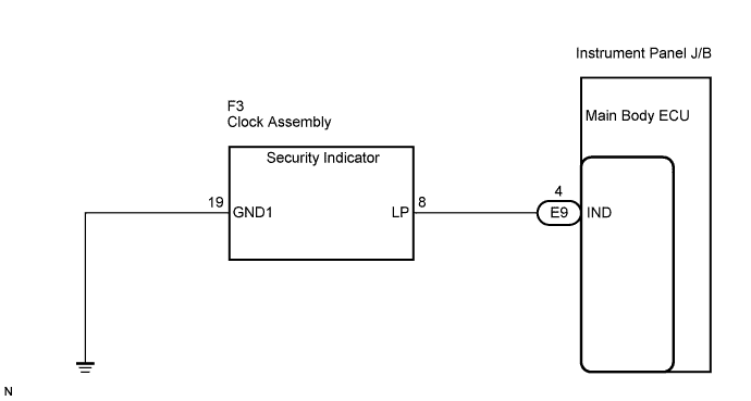
WIRING DIAGRAM
INSPECTION PROCEDURE
INSPECT CLOCK ASSEMBLY
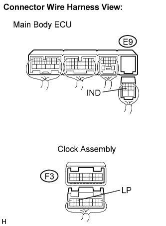
CHECK HARNESS AND CONNECTOR (CLOCK ASSEMBLY - MAIN BODY ECU)
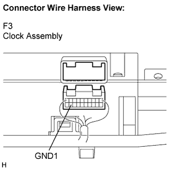
CHECK HARNESS AND CONNECTOR (CLOCK ASSEMBLY - BODY GROUND)
THEFT DETERRENT SYSTEM (w/o Entry and Start System) - Security Indicator Light Circuit |
DESCRIPTION
Even when the theft deterrent system is in the disarmed state, the security indicator blinks due to a signal output from the immobiliser system. The security indicator blinks continuously due to a continuous signal received from the immobiliser system while in the armed state.The main body ECU causes the security indicator to light up or blink only during the arming preparation state and alarm sounding states.
WIRING DIAGRAM
INSPECTION PROCEDURE
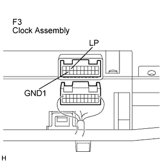
Disconnect the F3 clock connector.
Apply battery voltage between the terminals of the indicator, and check the lighting condition of the security indicator.
- Standard :
Measurement Condition
| Specified Condition
|
Battery positive (+) → Terminal F3-8 (LP)
Battery negative (-) → Terminal F3-19 (GND1)
| Lights up
|
- NOTICE:
- If the positive (+) lead and the negative (-) lead are incorrectly connected, the security indicator will not light up.
- Voltage of more than 12 V will damage the security indicator.
- If the voltage is too low, the security indicator will not light up.
| 2.CHECK HARNESS AND CONNECTOR (CLOCK ASSEMBLY - MAIN BODY ECU) |
Disconnect the E9 ECU connector.
Disconnect the F3 clock connector.
Measure the resistance according to the value(s) table below.
- Standard resistance:
Symbol (Tester Connection)
| Specified Condition
|
IND (E9-4) - LP (F3-8)
| Below 1 Ω
|
IND (E9-4) - Body ground
| 10 kΩ or higher
|
| | REPAIR OR REPLACE HARNESS OR CONNECTOR |
|
|
| 3.CHECK HARNESS AND CONNECTOR (CLOCK ASSEMBLY - BODY GROUND) |
Measure the resistance according to the value(s) in the table below.
- Standard resistance:
Symbol (Tester Connection)
| Specified Condition
|
GND1 (F3-19) - Body ground
| Below 1 Ω
|
| | REPAIR OR REPLACE HARNESS OR CONNECTOR |
|
|
| OK |
|
|
|
| PROCEED TO NEXT CIRCUIT INSPECTION SHOWN IN PROBLEM SYMPTOMS TABLE |
|