Theft Deterrent System (W/O Entry And Start System) Security Horn Circuit
DESCRIPTION
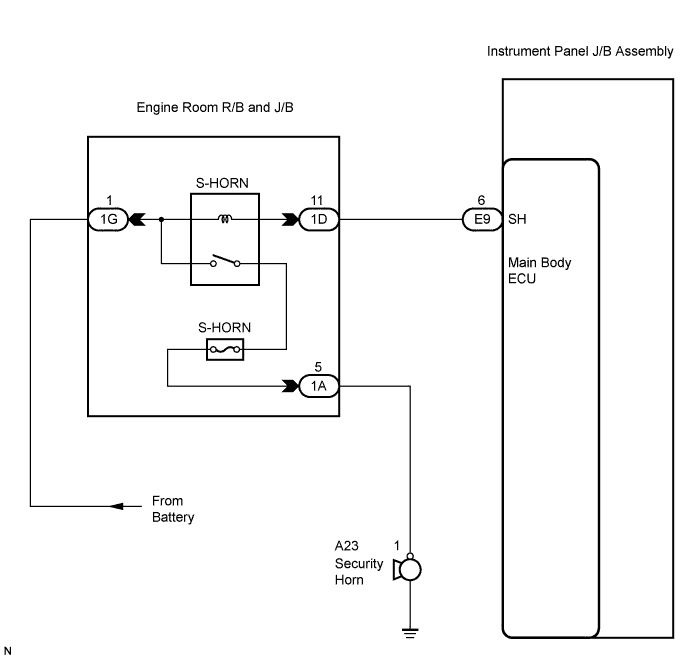
WIRING DIAGRAM
INSPECTION PROCEDURE
PERFORM ACTIVE TEST USING INTELLIGENT TESTER
INSPECT SECURITY HORN ASSEMBLY
CHECK HARNESS AND CONNECTOR (ENGINE ROOM J/B - SECURITY HORN ASSEMBLY)
CHECK HARNESS AND CONNECTOR (MAIN BODY ECU - ENGINE ROOM J/B)
CHECK HARNESS AND CONNECTOR (ENGINE ROOM J/B - BATTERY)
THEFT DETERRENT SYSTEM (w/o Entry and Start System) - Security Horn Circuit |
DESCRIPTION
When the theft deterrent system is changed from the armed state to the alarm sounding state, the main body ECU can control the security horn.
WIRING DIAGRAM
INSPECTION PROCEDURE
| 1.PERFORM ACTIVE TEST USING INTELLIGENT TESTER |
Connect the intelligent tester (with CAN VIM) to the DLC3.
Turn the ignition switch to the ON position.
Turn the intelligent tester main switch on.
Select the item below in the Active Test and then check that the horn sounds.
Main Body (Main Body ECU):Item
| Test Details
| Diagnostic Note
|
Security Horn
| Security horn ON/OFF
| -
|
- OK:
- The security horn sounds or stops correctly when operating it through the intelligent tester.
| OK |
|
|
|
| PROCEED TO NEXT CIRCUIT INSPECTION SHOWN IN PROBLEM SYMPTOMS TABLE |
|
| 2.INSPECT SECURITY HORN ASSEMBLY |
Remove the security horn assembly.
Check operation of the horn.
- Standard:
Measurement Condition
| Specified Condition
|
Battery positive (+) → Terminal 1
| Horn sounds
|
Battery negative (-) → Horn body
|
| | REPAIR OR REPLACE SECURITY HORN ASSEMBLY |
|
|
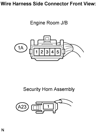
| 3.CHECK HARNESS AND CONNECTOR (ENGINE ROOM J/B - SECURITY HORN ASSEMBLY) |
Disconnect the 1A J/B connector and the A23 horn connector.
Measure the resistance according to the value(s) in the table below.
- Standard resistance:
Terminal Connection
| Specified Condition
|
1A-5 - A23-1
| Below 1 Ω
|
1A-5 - Body ground
| 10 kΩ or higher
|
| | REPAIR OR REPLACE HARNESS OR CONNECTOR |
|
|
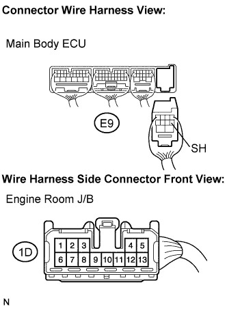
| 4.CHECK HARNESS AND CONNECTOR (MAIN BODY ECU - ENGINE ROOM J/B) |
Disconnect the E9 ECU connector and 1D J/B connector.
Measure the resistance according to the value(s) in the table below.
- Standard resistance:
Symbol (Terminal Connection)
| Specified Condition
|
SH (E9-6) - (1D-11)
| Below 1 Ω
|
SH (E9-6) - Body ground
| 10 kΩ or higher
|
| | REPAIR OR REPLACE HARNESS OR CONNECTOR |
|
|
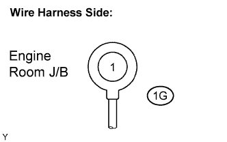
| 5.CHECK HARNESS AND CONNECTOR (ENGINE ROOM J/B - BATTERY) |
Disconnect the 1G J/B connector.
Measure the voltage according to the value(s) in the table below.
- Standard voltage:
Terminal Connection
| Specified Condition
|
1G-1 - Body ground
| 10 to 14 V
|
| | REPAIR OR REPLACE HARNESS OR CONNECTOR |
|
|
| OK |
|
|
|
| REPLACE ENGINE ROOM JUNCTION BLOCK ASSEMBLY |
|