Body Electrical. Camry. Acv40 Gsv40
Door Lock. Camry. Acv40 Gsv40
Wireless Door Lock Control System (W/O Entry And Start System) -- Diagnosis System |
| DESCRIPTION |
The diagnostic system allows for reading of the trouble codes from the DLC3.
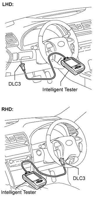
Use the intelligent tester to check and solve the problem.
| CHECK DLC3 |
The main body ECU uses ISO 157654-4 for communication protocol. The terminal arrangement of the DLC3 complies with ISO 15031-3 and matches the ISO 157654-4 format.
Symbols (Terminal No.) Terminal Description Condition Specified condition SIL (7) - SG (5) Bus "+" line During transmission Pulse generation CG (4) - Body ground Chassis ground Always Below 1 Ω SG (5) - Body ground Signal ground Always Below 1 Ω BAT (16) - Body ground Battery positive Always 11 to 14 V CANH (6) - CANL (14) HIGH-level CAN bus line Ignition switch OFF* 54 to 69 Ω CANH (6) - CG (4) HIGH-level CAN bus line Ignition switch OFF* 1 kΩ or higher CANL (14) - CG (4) HIGH-level CAN bus line Ignition switch OFF* 1 kΩ or higher CANH (6) - BAT (16) LOW-level CAN bus line Ignition switch OFF* 1 MΩ or higher CANL (14) - BAT (16) LOW-level CAN bus line Ignition switch OFF* 1 MΩ or higher - NOTICE:
- *: Before measuring the resistance, leave the vehicle as is for at least 1 minute and do not operate the ignition switch, any other switches or the doors.
Connect the cable of the intelligent tester to the DLC3, turn the ignition switch to the ON position and attempt to use the intelligent tester. If the screen displays a communication error message, a problem exists in the vehicle or in the tester.
- If communication is normal when the tool is connected to another vehicle, inspect the DLC3 on the original vehicle.
- If communication is still impossible when the tool is connected to another vehicle, the problem is probably in the tool itself. Consult the Service Department listed in the tool's instruction manual.
- If communication is normal when the tool is connected to another vehicle, inspect the DLC3 on the original vehicle.
 |
 |