Air Conditioning System -- System Description |
| GENERAL |
| Control | Outline |
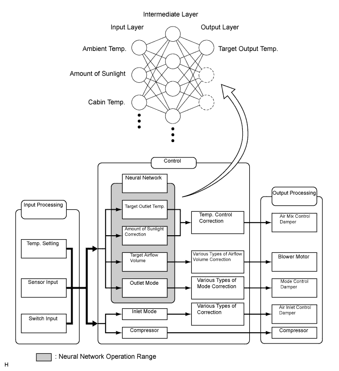
| Neural Network Control | This control is capable of effecting complex control by artificially simulating the information processing method of the nervous system of living organisms in order to establish a complex input / output relationship that is similar to a human brain. |
| Outlet Air Temp. Control | Based on the temperature set at the temperature control switch, the neural network control calculates the outlet air temperature based on the input signals from various sensors. |
| The temperature setting for the driver and front passenger are controlled independently in order to provide a separate vehicle interior temperatures for the right and left side of the cabin. Thus, air conditioning that accommodates the occupants' preferences has been realized. | |
| Blower Control | Controls the blower motor in accordance with the airflow volume that has been calculated by the neural network control based on the input signals from various sensors. |
| Air Outlet Control | Automatically switches the air outlets in accordance with the outlet mode that has been calculated by the neural network control based on the input signals from various sensors. |
| In accordance with the engine coolant temperature, outside air temperature, amount of sunlight, required blower, outlet temperature, and vehicle speed conditions, this control automatically switches the blower outlet to the FOOT / DEF mode to prevent the windows from becoming fogged when the outside air temperature is low. | |
| Air Inlet Control | Automatically controls the air inlet control damper to achieve the calculated required outlet air temperature. |
| Drives the servo motor (for air inlet) according to the operation of the air inlet control switch and moves the dampers to the FRESH or RECIRC position. | |
| Compressor Control | Through the calculation of the target evaporator temperature based on various sensor signals, the A/C amplifier optimally controls the discharge capacity by regulating the opening extent of the A/C compressor solenoid valve. |
| The A/C amplifier compares the A/C pulley speed signals, which are transmitted by the lock sensor located on the A/C compressor, with the engine speed signals, which are transmitted by the ECM (crankshaft position sensor). When the A/C amplifier determines that the A/C pulley is locked, it turns off the magnetic clutch. (for 2GR-FE) | |
| Rear Window Defogger Control | Switches the rear defogger and outside rear view mirror heaters on for 15 minutes when the rear defogger button is pressed. Switches them off if the button is pressed while they are operating. |
| Outside Temperature Indication Control | Calculates the outside temperature using signals transmitted by the outside temperature sensor. Calculated values are corrected by the A/C amplifier and then indicated on the multi-information display. |
| Self-Diagnosis | A DTC (Diagnostic Trouble Code) is stored in the memory when the A/C amplifier detects a problem with the air conditioning system. |
| NEURAL NETWORK CONTROL |
- In previous automatic air conditioning systems, the A/C amplifier determined the required outlet air temperature and blower air volume in accordance with the calculation formula that has been obtained based on information received from the sensors.
However, because the senses of a person are rather complex, a given temperature is sensed differently, depending on the environment in which the person is situated. For example, a given amount of solar radiation can feel comfortably warm in a cold climate, or extremely uncomfortable in a hot climate. Therefore, as a technique for effecting a higher level of control, a neural network has been adopted in the automatic air conditioning system. With this technique, the data that has been collected under varying environmental conditions is stored in the A/C amplifier. The A/C amplifier can then effect control to provide enhanced air conditioning comfort. - The neural network control consists of neurons in the input layer, intermediate layer, and output layer. The input layer neurons process the input data of the outside temperature, the amount of sunlight, and the room temperature based on the outputs of the switches and sensors, and output them to the intermediate layer neurons. Based on this data, the intermediate layer neurons adjust the strength of the links among the neurons. The sum of these is then calculated by the output layer neurons in the form of the required outlet temperature, solar correction, target airflow volume, and outlet mode control volume. Accordingly, the A/C amplifier controls the servo motors and blower motor in accordance with the control volumes that have been calculated by the neural network control.
| MODE POSITION AND DAMPER OPERATION |
Mode Position and Damper Operation
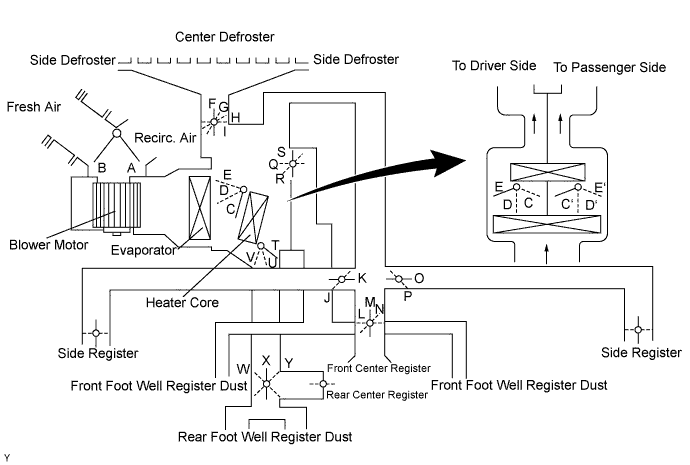
Functions of Main Dampers: Control Damper Operation Position Damper Position Operation Air Inlet Control Damper FRESH A Brings in fresh air. RECIRC B Recirculates internal air. Air Mix Control Damper MAX COLD to MAX HOT Temperature Setting C - D - E
(C' - D' - E')
T - U - VVaries the mixture ratio of the fresh air and the recirculation air in order to regulate the temperature continuously from HOT to COLD. Air Outlet Control Damper DEF 
F, J, L, P, S, Y Defrosts the windshield through the center defroster, side defroster, and side register. FOOT / DEF 
G, J, L, P, Q, X Defrosts the windshield through the center defroster, side defroster, side register, and rear center register, while air is also blown out from the front and rear foot well register ducts. FOOT 
H, J, L, P, Q, X Air blows out of the foot well register dust, and side register. In addition, air blows out slightly from the center defroster and side defroster. BI-LEVEL 
I, K, N, O, R, X Air blows out of the front and rear center registers, side register and front and rear foot well register ducts. FACE 
I, K, M, O, S, W Air blows out of the front and rear center registers, and side register.
| AIR OUTLETS AND AIRFLOW VOLUME |
Air Outlets and Airflow Volume
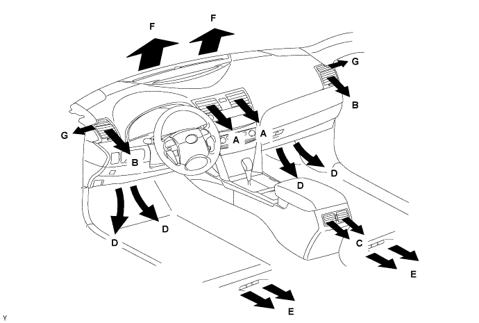
The size of the circle ○ indicates the proportion of airflow volume.INDICATION
(MODE)SELECTION
(Auto / Manual)FACE FOOT DEF CTR SIDE RR FR RR CTR SIDE A B C*6 D E F G
FACE○ / ○ 

B/L-U*1○ / ○ 

B/L-L*2○ / -
FOOT-F*3○ / ○ 
FOOT-R*4○ / -
FOOT-D*5○ / -
F/D○ / ○
DEF○ / ○
*1: Greater airflow volume at the upper area
*2: Greater airflow volume at the lower area
*3: Greater airflow volume at the front
*4: Greater airflow volume at the rear
*5: Greater airflow volume at the defroster
*6: Only for models with automatic air conditioning.
| PLASMACLUSTER ION GENERATOR CONTROL |
General:
A Plasmacluster ion generator is provided inside the air duct of the side register on the driver seat side to improve the air quality and comfort in the cabin.
This generator is controlled by the A/C amplifier and operates in conjunction with the blower motor.
- NOTICE:
- The Plasmacluster ion generator uses a high voltage, which is hazardous. Therefore, if the Plasmacluster ion generator requires repairs, be sure to have them done at a TOYOTA dealer.
- Do not apply any type of spray (such as a cleaning solvent or hair spray) or stick any foreign matter into the Plasmacluster ion outlet, as this could cause improper operation or a malfunction.
- After use, dust may accumulate around the side register on the driver seat side. If this occurs, press the OFF switch on the heater control panel to stop the blower motor before cleaning the area.
- It is normal for the Plasmacluster ion generator to emit a slight sound during operation. This sound is created when electrons collide with the electrode while Plasmacluster ions are being generated.
- HINT:
- PlasmaclusterTM, plasmacluster, and plasmacluster ions are a trademark of the SHARP Corporation.
Operation:
The Plasmacluster ion generator produces positive and negative ions from the water molecules (H2O) and oxygen molecules (O2) in the air, and emits them into the air.
The following 2 operation modes are available for the Plasmacluster generator, and these modes are switched alternately by the A/C ECU at intervals of 15 minutes. The operation mode status is indicated on the LCD in the heater control panel.
Operation Modes ION Generates negative ions and emits them into the air, thus providing the air quality in the cabin similar to the natural air, such as in forests or near waterfalls. CLEAN Generates positive and negative ions. When positive and negative ions are emitted into the air, they are quickly surrounded by water molecules and form cluster ions called Plasmacluster ions. Plasmacuster ions disperse around the cabin and bond with airborne particulates and molecules.
| BLOWER MOTOR |
| BUS CONNECTOR |
A BUS connector is used in the wire harness connection that connects the servo motor from the A/C amplifier.
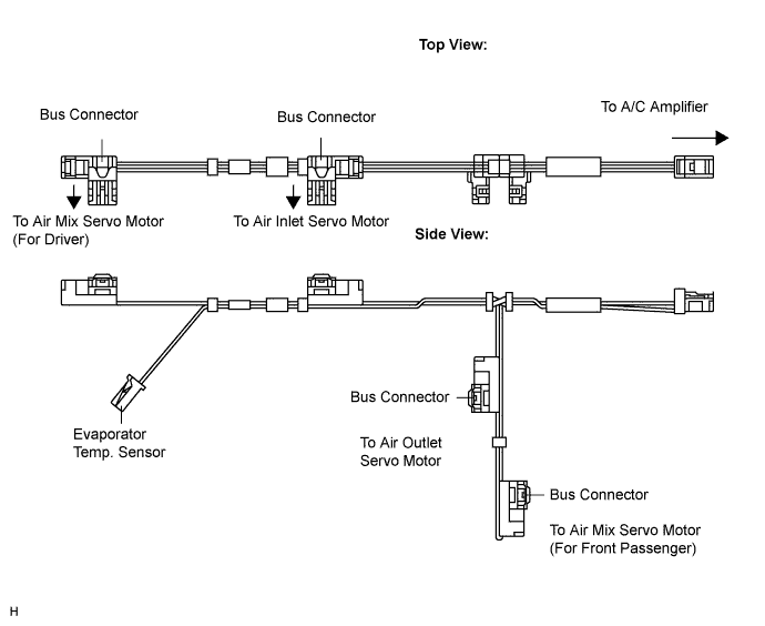
The BUS connector has a built-in communication/driver IC which communicates with each servo motor connector, actuates the servo motor, and has a position detection function. This enables bus communication for the servo motor wire harness, for a more lightweight construction and a reduced number of wires.
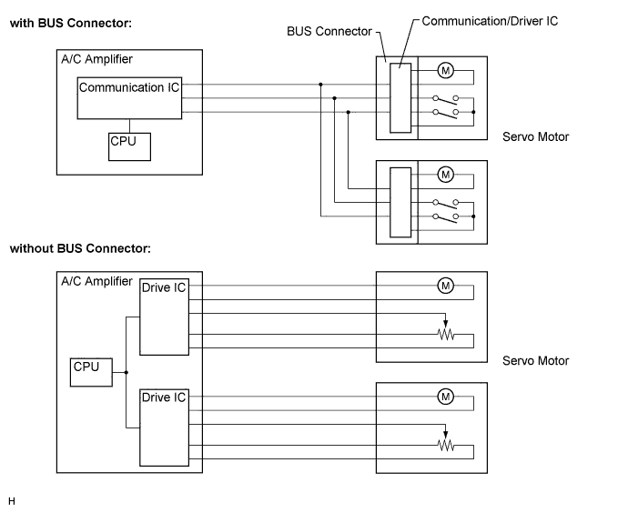
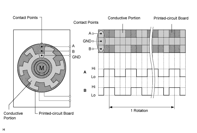
| SERVO MOTOR |
The pulse pattern type servo motor consists of a printed circuit board and servo motor. The printed circuit board has three contact points, and transmits to the A/C amplifier two ON-OFF signals for the difference of the pulse phase. The BUS connector detects the damper position and movement direction with this signal.
| A/C COMPRESSOR |
General
The A/C compressor is a continuously variable capacity type in which its capacity can be varied in accordance with the cooling load of the air conditioning.
This compressor consists of the A/C pulley, shaft, lug plate, swash plate, piston, shoe, crank chamber, cylinder, and solenoid valve.
The A/C pulley with built-in magnetic clutch and the lock sensor that detects whether the magnetic clutch is locked are installed on models with the 2GR-FE.
The DL (Damper Limiter) type A/C pulley is installed on models with the 2AZ-FE.
A solenoid valve that adjusts the suction pressure so that the compressor capacity can be controlled as desired is provided.
The internal valve is provided on models with 2AZ-FE to improve the A/C compressor durability under the high speed and large thermal load conditions. The internal valve is integrated into the solenoid valve.
Solenoid Valve Operation
The crank chamber is connected to the discharge passage. A solenoid valve is provided between the discharge passage (LO pressure) and the discharge passage (HI pressure).
The solenoid valve operates under duty cycle control in accordance with the signals from the A/C amplifier.
When the solenoid valve closes (solenoid coil is energized), a difference in pressure is created and the pressure in the crank chamber decreases. Then, the pressure that is applied to the right side of the piston becomes greater than the pressure that is applied to the left side of the piston. This compresses the spring and tilts the swash plate. As a result, the piston stroke increases and the discharge capacity increases.
When the solenoid valve opens (solenoid coil is not energized), the difference in pressure disappears. Then, the pressure that is applied to the left side of the piston becomes the same as the pressure that is applied to the right side of the piston. Thus, the spring elongates and eliminates the tilt of the swash plate. As a result, there is no piston stroke and the discharge capacity is reduced.
Internal Valve Operation (for 2AZ-FE)
The internal valve operates when the A/C compressor speed has increased rapidly, the A/C compressor speed is high, or when thermal load has suddenly changed. As a result, the A/C compressor capacity is reduced, increasing the durability of the A/C compressor.
DL type A/C Pulley (for 2AZ-FE)
This pulley contains a damper to absorb the torque fluctuations of the engine and a limiter mechanism to protect the drive belt in case the compressor locks. In the event that the compressor locks, the limiter mechanism causes the spoke portion of the pulley to break, thus separating the pulley from the compressor.
| LOCK SENSOR (for 2GR-FE) |
| ROOM TEMPERATURE SENSOR |
| AMBIENT TEMPERATURE SENSOR |
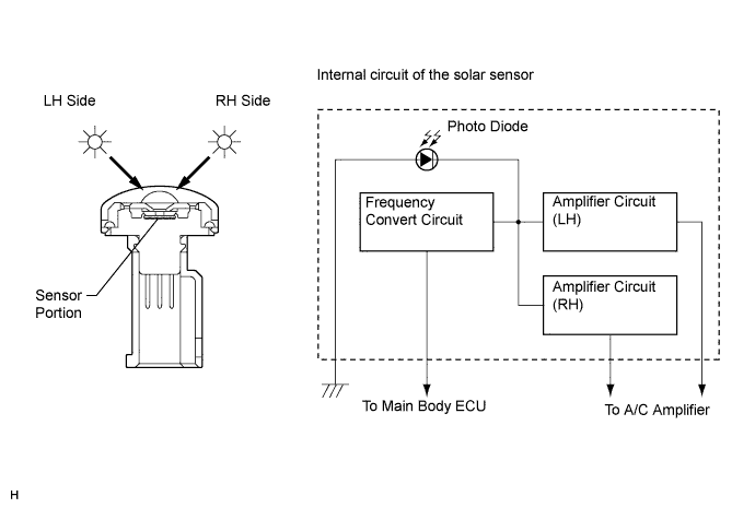
| SOLAR SENSOR |
The solar sensor consists of a photo diode, two amplifier circuits for the solar sensor, and frequency converter circuit for the light control sensor.
A solar sensor detects (in the form of changes in the current that flows through the built-in photo diode) the changes in the amount of sunlight from the LH and RH sides (2 directions) and outputs these sunlight strength signals to the A/C amplifier.
| EVAPORATOR TEMPERATURE SENSOR |
| A/C PRESSURE SENSOR |