Air Conditioning System Heater Control Panel Power Source Circuit
DESCRIPTION
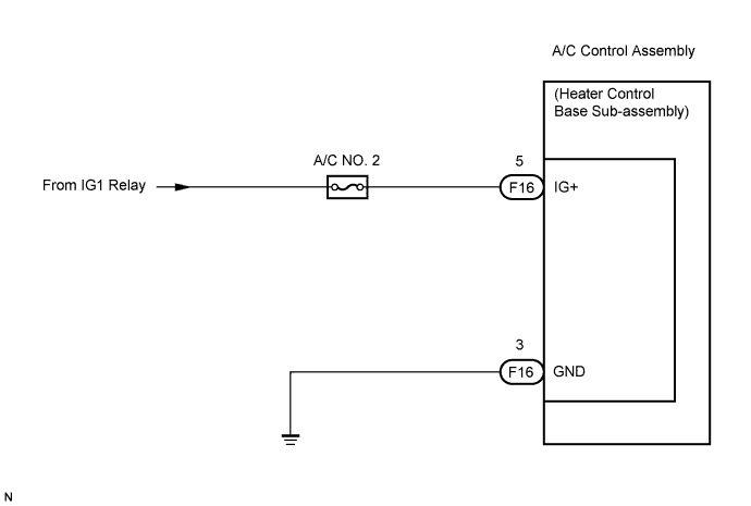
WIRING DIAGRAM
INSPECTION PROCEDURE
CHECK HARNESS AND CONNECTOR (IG+ - BODY GROUND)
CHECK HARNESS AND CONNECTOR (GND - BODY GROUND)
AIR CONDITIONING SYSTEM - Heater Control Panel Power Source Circuit |
DESCRIPTION
Battery voltage is supplied to the A/C control assembly (heater control base sub-assembly) through the A/C No. 2 fuse.
WIRING DIAGRAM
INSPECTION PROCEDURE
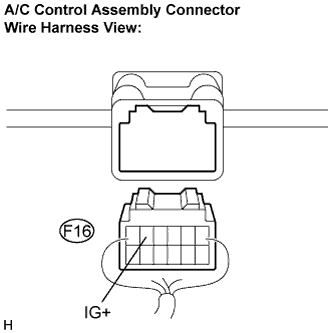
| 1.CHECK HARNESS AND CONNECTOR (IG+ - BODY GROUND) |
Disconnect the connector from the A/C control assembly (heater control base sub-assembly).
Measure the voltage according to the value(s) in the table below.
- Standard voltage:
Tester Connection
(Symbols)
| Condition
| Specified Condition
|
F16-5 (IG+) - Body ground
| Ignition switch: ON
| 10 to 14 V
|
F16-5 (IG+) - Body ground
| Ignition switch: LOCK
| Below 1 V
|
| | REPAIR OR REPLACE HARNESS OR CONNECTOR |
|
|
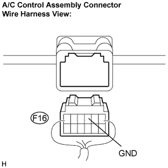
| 2.CHECK HARNESS AND CONNECTOR (GND - BODY GROUND) |
Measure the resistance according to the value(s) in the table below.
- Standard resistance:
Tester Connection
(Symbols)
| Condition
| Specified Condition
|
F16-3 (GND) - Body ground
| Always
| Below 1 Ω
|
| | REPAIR OR REPLACE HARNESS OR CONNECTOR |
|
|
| OK |
|
|
|
| PROCEED TO NEXT CIRCUIT INSPECTION SHOWN IN PROBLEM SYMPTOMS TABLE |
|