Dtc B2271 Ignition Hold Monitor Malfunction
DESCRIPTION
WIRING DIAGRAM
INSPECTION PROCEDURE
CHECK DTC OUTPUT
INSPECT FUSE (AM2)
CHECK WIRE HARNESS (MAIN BODY ECU - BATTERY)
DTC B2271 Ignition Hold Monitor Malfunction |
DESCRIPTION
This DTC is output when a problem such as an open in the AM2 fuse, an open or short in the wire harness between the fuse and main body ECU, a short in the IG output circuit inside the main body ECU, a short between the main body ECU and relay, and a short in the relay is detected.- HINT:
- When the main body ECU is replaced with a new one and the negative (-) battery terminal is connected, the power source mode becomes the IG-ON mode. When the battery is removed and reinstalled, the power source mode that was selected when the battery was removed is restored.
- After the main body ECU is replaced, perform the registration procedures for the engine immobiliser system.
DTC No.
| DTC Detection Condition
| Trouble Area
|
B2271
| Hold circuit, IG1 relay actuation circuit or IG2 relay actuation circuit inside main body ECU is open or shorted
| - AM2 fuse
- Main body ECU
- Wire harness or connector
|
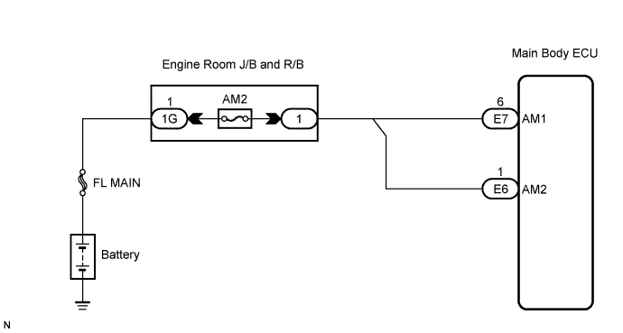
WIRING DIAGRAM
INSPECTION PROCEDURE
Clear the DTCs (CAMRY_ACV40 RM000000YEH05QX.html).
- HINT:
- After all DTCs are cleared, check if the trouble occurs again 6 seconds after the engine switch is turned on (IG).
Check for DTCs again.
- OK:
- DTC is not output.
Remove the AM2 fuse from the engine room J/B.
Measure the resistance of the fuse.
- Standard Resistance:
Tester Connection
| Condition
| Specified Condition
|
AM2 fuse
| Always
| Below 1 Ω
|
| 3.CHECK WIRE HARNESS (MAIN BODY ECU - BATTERY) |
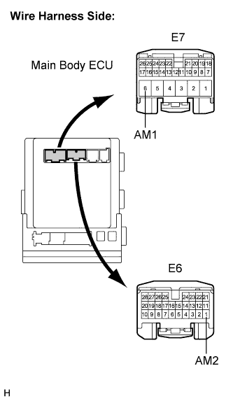
Disconnect the E6 and E7 ECU connectors.
Measure the voltage according to the value(s) in the table below.
- Standard Voltage:
Tester Connection
| Condition
| Specified Condition
|
E7-6 (AM1) - Body ground
| Always
| 11 to 14 V
|
E6-1 (AM2) - Body ground
| Always
| 11 to 14 V
|
| | REPAIR OR REPLACE HARNESS OR CONNECTOR |
|
|