Anti-Lock Brake System -- Test Mode Procedure |
| WARNING LIGHT AND INDICATOR LIGHT INITIAL CHECK |
Release the parking brake.
- NOTICE:
- Before releasing the parking brake, move the shift lever to the P position for safety (AT model) or set the chocks to hold the vehicle for safety (MT model).
- HINT:
- When the parking brake is applied or the level of the brake fluid is low, the BRAKE warning light comes on.
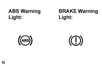
When the ignition switch is turned to the ON position, check that the ABS warning light comes on for approximately 3 seconds.
- HINT:
- If the skid control ECU stores any DTCs, the ABS and BRAKE warning lights come on.
- If the indicator remains on or does not come on, proceed to troubleshooting for the light circuits listed below.
Trouble Area See procedure ABS warning light (Remains on) CAMRY_ACV40 RM000001JD300QX.html ABS warning light circuit (Does not come on) CAMRY_ACV40 RM000001JD400QX.html BRAKE warning light (Remains on) CAMRY_ACV40 RM000001JD800OX.html BRAKE warning light (Does not come on) CAMRY_ACV40 RM000001JDC00OX.html
 |
| SENSOR SIGNAL CHECK USING TEST MODE (SIGNAL CHECK) (INTELLIGENT TESTER) |
- HINT:
- DTCs are stored if any malfunctions are detected during each sensor check.
Procedure to enter Test Mode.
Turn the ignition switch off.
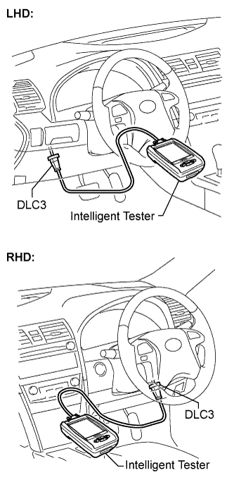
Connect the intelligent tester to the DLC3.
Check that the steering wheel is centered and move the shift lever to the P position (for Automatic Transaxle) or apply the parking brake (Manual Transaxle).
Turn the ignition switch to the ON position.
Set the intelligent tester to Test Mode (select "SIGNAL CHECK").
- HINT:
- Refer to the intelligent tester operator's manual for further details.
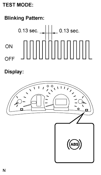
Check that the ABS warning light comes on for several seconds and then blinks in test mode.
- HINT:
- If the ABS warning light does not blink, inspect the ABS warning light circuit.
Trouble Area See procedure ABS warning light (Remains on) CAMRY_ACV40 RM000001JD300QX.html

Check the sensor signal.
Drive the vehicle straight ahead.
Accelerate the vehicle to a speed of 45 km/h (28 mph) or more for several seconds and check that the ABS warning light goes off when the brake pedal is depressed.- HINT:
- The sensor check may not be completed if wheel spin occurs, or if the steering wheel is turned during this check.
- The ABS warning light goes off when the sensor signal check has been completed and the brake pedal is depressed.
- The ABS warning light comes on immediately after a malfunction has been detected during the speed sensor signal check.
Stop the vehicle.
- NOTICE:
- The speed sensor check may not be completed if the speed sensor check is started while turning the steering wheel or spinning the wheels.
- If the signal check has not been completed, the ABS warning light will blink while driving and the ABS system will not operate.
Read the DTC(s) by following the tester screen.
- NOTICE:
- If only the DTCs are displayed, repair the malfunction area and clear the DTCs.
- If the DTCs or Test Mode codes (DTC of signal check function) are displayed, repair the malfunction area, clear the DTCs and perform the Test Mode inspection.
- HINT:
- See the list of DTCs (See procedure "A").
 |
| SENSOR SIGNAL CHECK BY TEST MODE (SIGNAL CHECK) (SST CHECK WIRE) |
- HINT:
- DTCs are stored if any malfunctions are detected during each sensor check.
Procedure for Test Mode.
Turn the ignition switch off.
Check that the steering wheel is centered and move the shift lever to the P position (Automatic Transaxle) or apply the parking brake (Manual Transaxle).
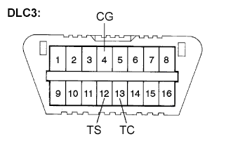
Using SST, connect terminals TS and CG of the DLC3.
- SST
- 09843-18040
Turn the ignition switch to the ON position.
Check that the ABS warning light comes on for several seconds and then blinks in Test Mode.
- HINT:
- If the ABS warning light does not blink, inspect the TS and CG terminal circuit, and ABS warning light circuit.
Trouble Area See procedure TS and CG terminal circuit CAMRY_ACV40 RM000000XIV00JX.html ABS warning light circuit (Remains on) CAMRY_ACV40 RM000001JD300QX.html ABS warning light circuit (Does not come on) CAMRY_ACV40 RM000001JD400QX.html

Check the sensor signal.
Drive the vehicle straight ahead.
Accelerate the vehicle to a speed of 45 km/h (28 mph) or more for several seconds and check that the ABS warning light goes off when the brake pedal is depressed.- HINT:
- The sensor check may not be completed if wheel spin occurs, or if the steering wheel is turned during this check.
- The ABS warning light goes off when the sensor signal check has been completed and the brake pedal is depressed.
- The ABS warning light comes on immediately after a malfunction has been detected during the speed sensor signal check.
Stop the vehicle.
- NOTICE:
- The speed sensor check may not be completed if the speed sensor check is started while turning the steering wheel or spinning the wheels.
- If the signal check has not been completed, the ABS warning light will blink while driving and the ABS system will not operate.
Using SST, connect terminals TC and CG of the DLC3.
- SST
- 09843-18040
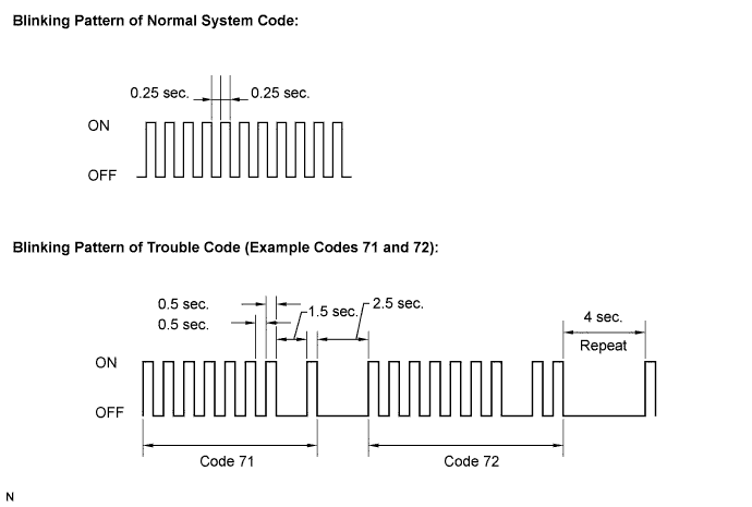
Count the number of blinks of the ABS warning light.
- NOTICE:
- If only the DTCs are displayed, repair the malfunction area and clear the DTCs.
- If the DTCs or Test Mode codes (DTC of signal check function) are displayed, repair the malfunction area, clear the DTCs and perform the Test Mode inspection.
- HINT:
- If more than 1 malfunction is detected at the same time, the lowest numbered code will be displayed first.
- See the list of DTCs (See procedure "A").
After performing the check, disconnect the SST from terminals TS and CG, and TC and CG of the DLC3, and turn the ignition switch off.
Turn the ignition switch to the ON position to cancel the test mode.
- HINT:
- If the ignition switch is not turned to the ON position after the SST is removed from the DLC3, the previous Test Mode will continue.
- If the ignition switch is turned to the ON position with terminals TS and CG shorted, the previous Test Mode will continue.
 |
| DTC OF TEST MODE (SIGNAL CHECK) FUNCTION (Procedure "A") |
| Code No. | Diagnosis | Trouble Area |
| C1271/71 | Low output signal of front speed sensor RH |
|
| C1272/72 | Low output signal of front speed sensor LH |
|
| C1273/73 | Low output signal of rear speed sensor RH |
|
| C1274/74 | Low output signal of rear speed sensor LH |
|
| C1275/75 | Abnormal change in output signal of front speed sensor RH |
|
| C1276/76 | Abnormal change in output signal of front speed sensor LH |
|
| C1277/77 | Abnormal change in output signal of rear speed sensor RH |
|
| C1278/78 | Abnormal change in output signal of rear speed sensor LH |
|
- HINT:
- The codes in this table are output only in Test Mode (signal check).