Rear Axle Carrier Installation
INSTALL REAR AXLE CARRIER SUB-ASSEMBLY
TEMPORARILY TIGHTEN REAR NO. 1 SUSPENSION ARM
TEMPORARILY TIGHTEN REAR NO. 2 SUSPENSION ARM
TEMPORARILY TIGHTEN REAR STRUT ROD
INSTALL REAR AXLE HUB AND BEARING ASSEMBLY
INSPECT REAR AXLE HUB BEARING LOOSENESS
INSPECT REAR AXLE HUB RUNOUT
INSTALL REAR DISC
INSTALL REAR DISC BRAKE CALIPER ASSEMBLY
INSTALL REAR WHEEL
STABILIZE SUSPENSION
FULLY TIGHTEN REAR NO. 1 SUSPENSION ARM
FULLY TIGHTEN REAR NO. 2 SUSPENSION ARM
FULLY TIGHTEN REAR STRUT ROD
INSTALL REAR HEIGHT CONTROL SENSOR SUB-ASSEMBLY RH (w/ HID Headlight System)
ADJUST REAR WHEEL ALIGNMENT
HEIGHT CONTROL SENSOR SIGNAL INITIALIZATION (w/ HID Headlight System)
CHECK ABS SPEED SENSOR SIGNAL
Rear Axle Carrier -- Installation |
| 1. INSTALL REAR AXLE CARRIER SUB-ASSEMBLY |
Install the rear axle carrier sub-assembly to the shock absorber with the 2 bolts and 2 nuts.
- Torque:
- 180 N*m{1,836 kgf*cm, 133 ft.*lbf}
| 2. TEMPORARILY TIGHTEN REAR NO. 1 SUSPENSION ARM |
Temporarily tighten the rear No. 1 suspension arm with the bolt and nut.
- HINT:
- Insert the bolt from the rear side of the vehicle and temporarily tighten the bolt.
| 3. TEMPORARILY TIGHTEN REAR NO. 2 SUSPENSION ARM |
Temporarily tighten the rear No. 2 suspension arm with the bolt and nut.
- HINT:
- Insert the bolt from the rear side of the vehicle and temporarily tighten the bolt.
| 4. TEMPORARILY TIGHTEN REAR STRUT ROD |
Temporarily tighten the rear strut rod with the bolt and nut.
- HINT:
- Insert the bolt from the inside of the vehicle and temporarily tighten the bolt.
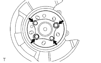
| 5. INSTALL REAR AXLE HUB AND BEARING ASSEMBLY |
Install the hub and bearing assembly with the 4 bolts.
- Torque:
- 80 N*m{816 kgf*cm, 59 ft.*lbf}
Connect the skid control sensor connector.
- NOTICE:
- Do not twist the sensor wire when connecting it.
| 6. INSPECT REAR AXLE HUB BEARING LOOSENESS |
Using a dial indicator, check for looseness near the center of the axle hub.
- Maximum:
- 0.05 mm (0.0020 in.)
- NOTICE:
- Ensure that the dial indicator is set perpendicular to the measurement surface.
If looseness exceeds the maximum, replace the axle hub assembly.
| 7. INSPECT REAR AXLE HUB RUNOUT |
Using a dial indicator, check for runout on the surface of the axle hub outside the hub bolt.
- Maximum:
- 0.07 mm (0.0027 in.)
- NOTICE:
- Ensure that the dial indicator is set perpendicular to the measurement surface.
If runout exceeds the maximum, replace the axle hub assembly.
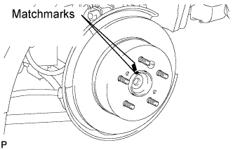
Aligning the matchmarks, install the rear disc.
- HINT:
- When replacing the rear disc with a new one, select the installation position where the rear disc has the minimum runout.
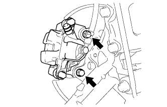
| 9. INSTALL REAR DISC BRAKE CALIPER ASSEMBLY |
Install the rear disc brake caliper with the 2 bolts.
- Torque:
- 62 N*m{630 kgf*cm, 46 ft.*lbf}
- NOTICE:
- Do not twist the brake hose when installing the rear disc brake caliper assembly LH.
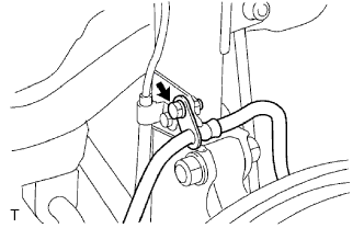
Install the rear flexible hose with the bolt.
- Torque:
- 19 N*m{192 kgf*cm, 14 ft.*lbf}
- Torque:
- 103 N*m{1,050 kgf*cm, 76 ft.*lbf}
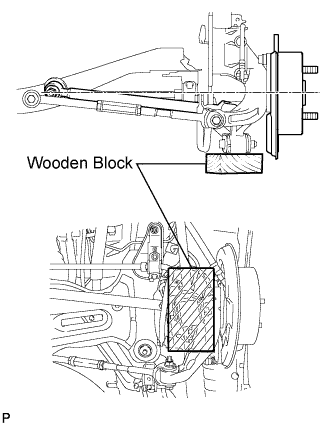
Jack up the rear axle carrier, placing a wooden block to avoid damage. Apply load to the suspension so that the installed bolt of the rear suspension No. 1 arm (inner side of vehicle) is horizontally aligned with the center of the rear axle hub.
| 12. FULLY TIGHTEN REAR NO. 1 SUSPENSION ARM |
Fully tighten the bolt.
- Torque:
- 100 N*m{1,020 kgf*cm, 74 ft.*lbf}
| 13. FULLY TIGHTEN REAR NO. 2 SUSPENSION ARM |
Fully tighten the bolt.
- Torque:
- 100 N*m{1,020 kgf*cm, 74 ft.*lbf}
| 14. FULLY TIGHTEN REAR STRUT ROD |
Fully tighten the bolt.
- Torque:
- 113 N*m{1,150 kgf*cm, 83 ft.*lbf}
| 15. INSTALL REAR HEIGHT CONTROL SENSOR SUB-ASSEMBLY RH (w/ HID Headlight System) |
- HINT:
- Perform the procedure only when installing the RH side. (CAMRY_ACV40 RM0000011E000WX_01_0012.html)
| 16. ADJUST REAR WHEEL ALIGNMENT |
- HINT:
- CAMRY_ACV40 RM0000011DQ017X.html
| 17. HEIGHT CONTROL SENSOR SIGNAL INITIALIZATION (w/ HID Headlight System) |
- HINT:
- CAMRY_ACV40 RM000002CE400KX.html
| 18. CHECK ABS SPEED SENSOR SIGNAL |
ABS: CAMRY_ACV40 RM000001JBD011X.html
VSC: CAMRY_ACV40 RM000000XHT028X.html