Blower Unit -- Removal |
| 1. PRECAUTION |
- NOTICE:
- After the ignition switch is turned off, the navigation receiver assembly (HDD navigation system) records various types of memory and settings. As a result, after turning the ignition switch off, make sure to wait at least 60 seconds before disconnecting the cable from the negative (-) battery terminal.
| 2. RECOVER REFRIGERANT FROM REFRIGERATION SYSTEM |
Start up the engine.
Turn the A/C switch on.
Operate the cooler compressor at an engine speed of approximately 1,000 rpm for 5 to 6 minutes to circulate the refrigerant. This causes most of the compressor oil from the various components of the A/C system to collect in the A/C compressor.
Stop the engine.
Recover the refrigerant from the A/C system using a refrigerant recovery unit.
| 3. ALIGN FRONT WHEELS FACING STRAIGHT AHEAD |
| 4. DISCONNECT BATTERY NEGATIVE TERMINAL |
- CAUTION:
- Wait for 90 seconds after disconnecting the terminal to prevent the airbag from deploying. (CAMRY_ACV40 RM000000KT10BKX.html)
| 5. REMOVE FRONT WIPER ARM AND BLADE ASSEMBLY LH |
Remove the nut and the front wiper arm and blade assembly LH.
 |
| 6. REMOVE FRONT WIPER ARM AND BLADE ASSEMBLY RH |
Remove the nut and the front wiper arm and blade assembly RH.
 |
| 7. REMOVE FRONT FENDER TO COWL SIDE SEAL LH |
Disengage the claw and remove the front fender to cowl side seal LH.
 |
| 8. REMOVE FRONT FENDER TO COWL SIDE SEAL RH |
Disengage the claw and remove the front fender to cowl side seal RH.
 |
| 9. REMOVE COWL TOP VENTILATOR LOUVER SUB-ASSEMBLY |
Remove the 2 clips.
 |
Disengage the 4 claws and remove the cowl top ventilator louver sub-assembly.
| 10. REMOVE WINDSHIELD WIPER MOTOR AND LINK ASSEMBLY |
Disconnect the connector.
 |
Remove the 4 bolts and the windshield wiper motor and link assembly.
 |
| 11. REMOVE COWL TOP OUTER FRONT PANEL SUB-ASSEMBLY |
Disengage the clamp.
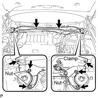 |
Remove the 4 nuts, the 4 bolts and the cowl top outer front panel sub-assembly.
| 12. DISCONNECT SUCTION PIPE SUB-ASSEMBLY |
Remove the bolt, and slide the hook connector.
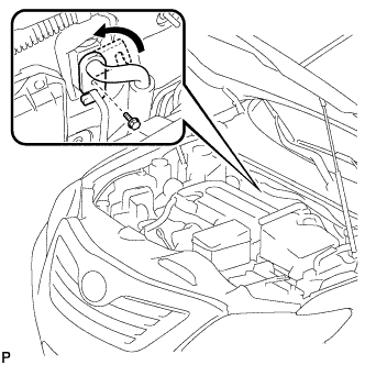 |
Disconnect the suction pipe sub-assembly.
Remove the O-ring from the suction hose sub-assembly.
- NOTICE:
- Seal the openings of the disconnected parts using vinyl tape to prevent entry of moisture and foreign matter.
| 13. DISCONNECT AIR CONDITIONING TUBE AND ACCESSORY |
Disconnect the air conditioning tube and accessory.
Remove the O-ring from the air conditioner tube and accessory.
- NOTICE:
- Seal the openings of the disconnected parts using vinyl tape to prevent entry of moisture and foreign matter.
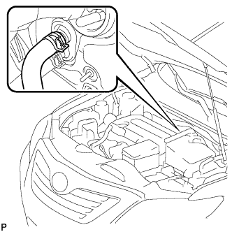
| 14. DISCONNECT HEATER OUTLET WATER HOSE |
Using pliers, grip the claws of the clip and slide the clip to disconnect the heater outlet water hose.
- NOTICE:
- Do not apply excessive force to the heater outlet water hose.
- Prepare a drain pan or cloth in case the coolant leaks.
 |
| 15. DISCONNECT HEATER INLET WATER HOSE |
- HINT:
- Disconnection procedure for the heater inlet water hose is the same as that for the heater outlet water hose.
| 16. REMOVE INSTRUMENT PANEL SAFETY PAD ASSEMBLY |
Remove the instrument panel safety pad assembly (CAMRY_ACV40 RM0000024DD078X.html).
| 17. REMOVE NO. 1 CONSOLE BOX DUCT (w/ Rear Register Duct) |
Remove the clip and No. 1 console box duct.
 |
| 18. REMOVE FLOOR CARPET BRACKET LH |
Release the clamp.
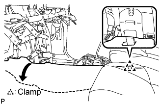 |
Turn back the floor carpet.
Remove the 3 clips.
 |
Remove the floor carpet bracket LH.
| 19. REMOVE FLOOR CARPET BRACKET RH |
Release the clamp.
 |
Turn back the floor carpet.
Remove the 3 clips.
 |
Remove the floor carpet bracket RH.
| 20. REMOVE REAR NO. 2 AIR DUCT |
Release the 2 claws and remove the rear No. 2 air duct.
 |
| 21. REMOVE REAR NO. 1 AIR DUCT |
Release the 2 claws and remove the rear No. 1 air duct.
 |
| 22. REMOVE NO. 1 AIR DUCT |
Disengage the 2 claws and remove the No. 1 air duct.
 |
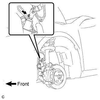
| 23. REMOVE STEERING COLUMN ASSEMBLY |
Remove the clamp from the steering column hole shield.
 |
Remove the bolt and slide the steering intermediate shaft assembly.
- NOTICE:
- Do not separate the steering intermediate shaft assembly from the power steering link assembly.
 |
Put matchmarks on the steering intermediate shaft assembly and the power steering link assembly.
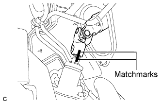 |
Separate the steering intermediate shaft assembly from the power steering link assembly.
Disconnect the connectors and wire harness clamps from the steering column assembly.
Remove the bolt, 2 nuts and the steering column assembly.
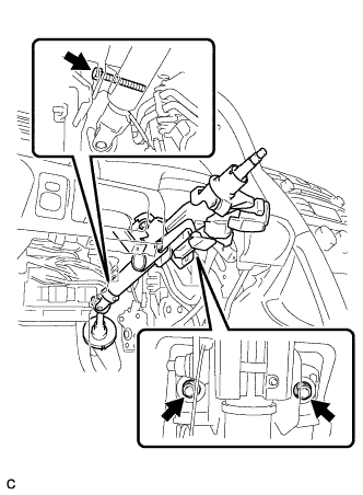 |
| 24. REMOVE AIR CONDITIONING AMPLIFIER ASSEMBLY |
Disconnect the 2 connectors.
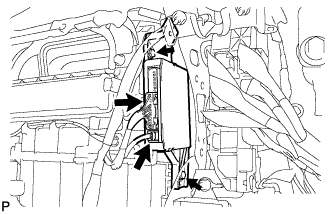 |
Remove the 2 bolts and air conditioning amplifier assembly.
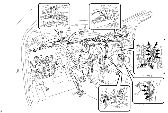
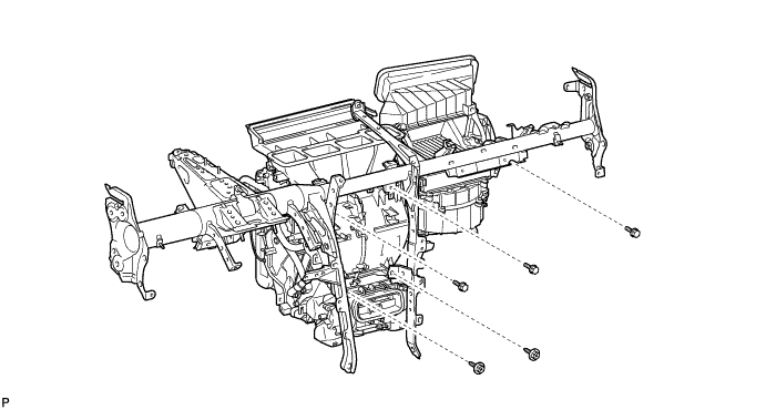
| 25. REMOVE INSTRUMENT PANEL REINFORCEMENT ASSEMBLY |
Remove the 28 clamps, disconnect the 11 connectors, and then disconnect the wire harness.
Remove the 6 nuts, 7 bolts, and junction block.
Remove the 2 caps and 2 bolts from the engine compartment side.
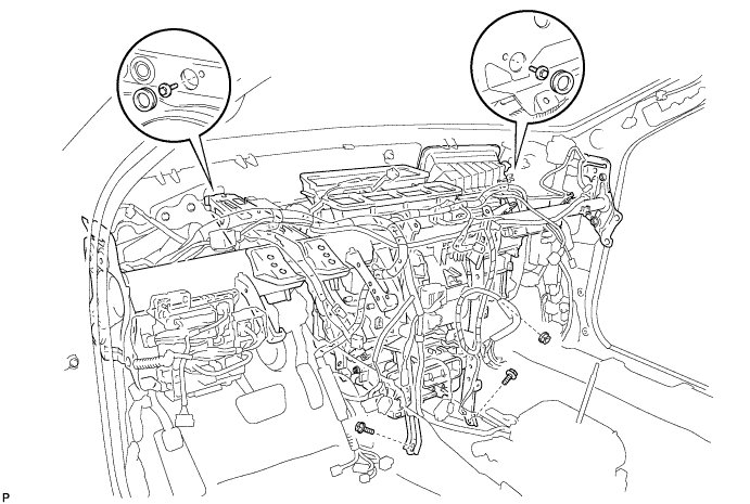
Remove the 2 bolts and nut.
Using a "TORX" socket wrench (T40), remove the 5 "TORX" bolts.
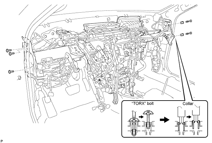
- HINT:
- The "TORX" bolts on the passenger side can be removed with the collars for adjustment.
Using a hexagon wrench 12 mm, remove the 2 collars and instrument panel reinforcement assembly with the air conditioner unit assembly.
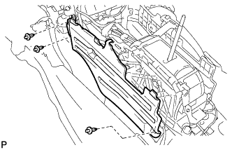
Remove the 3 bolts, 2 screws, and instrument panel reinforcement assembly.
| 26. REMOVE BLOWER ASSEMBLY |
Disconnect the connector.
 |
Remove the 2 screws and blower assembly.