INSTALL RADIO TUNER OPENING COVER WITH HEATER CONTROL PANEL ASSEMBLY (w/o Radio Receiver)
INSTALL RADIO RECEIVER WITH HEATER CONTROL PANEL ASSEMBLY (w/ Radio Receiver)
INSTALL LOWER INSTRUMENT CLUSTER FINISH PANEL CENTER SUB-ASSEMBLY
INSTALL UPPER CONSOLE REAR PANEL SUB-ASSEMBLY (for Automatic Transaxle)
INSTALL UPPER CONSOLE REAR PANEL SUB-ASSEMBLY (for Manual Transaxle)
INSTALL FLOOR SHIFT POSITION INDICATOR HOUSING SUB-ASSEMBLY (for Automatic Transaxle)
INSTALL SHIFT LEVER KNOB SUB-ASSEMBLY (for Automatic Transaxle)
INSTALL SHIFT LEVER KNOB SUB-ASSEMBLY (for Manual Transaxle)
INSTALL TURN SIGNAL SWITCH ASSEMBLY WITH SPIRAL CABLE SUB-ASSEMBLY
Blower Unit -- Installation |
| 1. INSTALL BLOWER ASSEMBLY |
Install the blower assembly with the 2 screws.
 |
Connect the connector.
| 2. INSTALL INSTRUMENT PANEL REINFORCEMENT ASSEMBLY |
Install the conditioner unit assembly to the instrument panel reinforcement assembly with the 2 screws and 3 bolts.
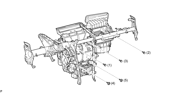
- Torque:
- 9.8 N*m{100 kgf*cm, 87 in.*lbf}
- NOTICE:
- Tighten the bolts and screws in the order shown in the illustration to install the air conditioner unit assembly.
Driver seat:
Using a "TORX" socket wrench (T40), install the instrument panel reinforcement assembly with the 3 "TORX" bolts.

- Torque:
- 17 N*m{173 kgf*cm, 13 ft.*lbf}
Passenger seat:
Using a 12 mm hexagon wrench, adjust the position of the 2 collars.
- Torque:
- 6.0 N*m{61 kgf*cm, 53 in.*lbf}
Using a "TORX" socket wrench (T40), install the instrument panel reinforcement assembly with the 2 "TORX" bolts.
- Torque:
- 20 N*m{204 kgf*cm, 15 ft.*lbf}
Install the instrument panel reinforcement assembly with the 2 bolts and nut.
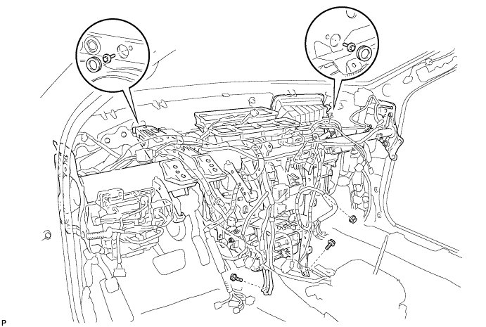
- Torque:
- 9.8 N*m{100 kgf*cm, 87 in.*lbf}(NUT)
Install the 2 bolts and 2 caps.
- Torque:
- 17 N*m{175 kgf*cm, 13 ft.*lbf}
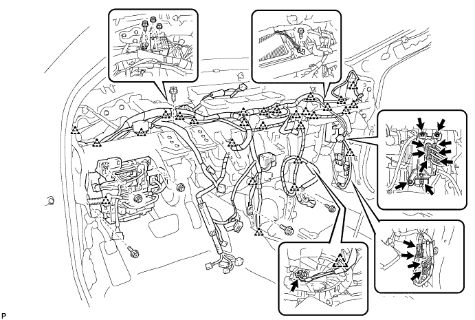
Connect the connectors and clamps.
Install the 6 nuts and 7 bolts.
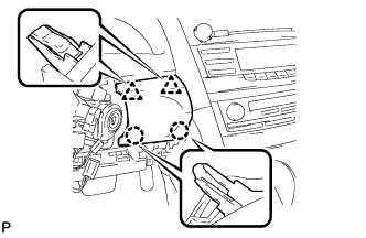
| 3. INSTALL STEERING COLUMN ASSEMBLY |
Install the steering column assembly with the bolt and 2 nuts.
- Torque:
- 21 N*m{214 kgf*cm, 16 ft.*lbf}
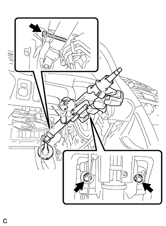 |
Connect the connectors and wire harness clamps to the steering column assembly.
Align the matchmarks on the steering intermediate shaft assembly and the power steering link assembly.
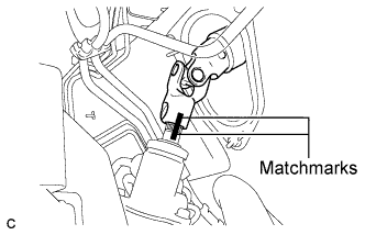 |
Install the bolt.
- Torque:
- 35 N*m{360 kgf*cm, 26 ft.*lbf}
 |
Install the clamp to the steering column hole shield.
 |
| 4. INSTALL NO. 1 AIR DUCT |
Engage the 2 claws to install the No. 1 air duct.
 |
| 5. INSTALL REAR NO. 1 AIR DUCT |
Engage the 2 claws to install the rear No. 1 air duct.
 |
| 6. INSTALL REAR NO. 2 AIR DUCT |
Engage the 2 claws to install the rear No. 2 air duct.
 |
| 7. INSTALL FLOOR CARPET BRACKET RH |
| 8. INSTALL FLOOR CARPET BRACKET LH |
| 9. INSTALL NO. 1 CONSOLE BOX DUCT (w/ Rear Register Duct) |
Install the No. 1 console box duct with the clip.
 |
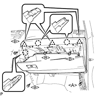
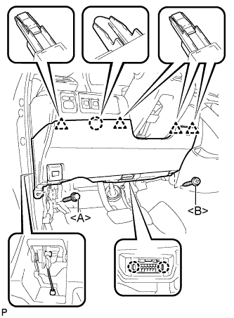
| 10. INSTALL INSTRUMENT PANEL SAFETY PAD ASSEMBLY |
Engage the 5 claws.
- NOTICE:
- Do not allow the wire harness to get caught in the claws.
Install the 2 bolts <H> or <O> and 2 nuts <C> or <I>.

Engage each clamp.
Install the bolt <J>.
- Torque:
- 7.0 N*m{71 kgf*cm, 62 in.*lbf}
Install the 2 passenger airbag bolts <K>.
- Torque:
- 20 N*m{204 kgf*cm, 15 ft.*lbf}
Connect each connector and install the instrument panel safety pad assembly.
with Plasmacluster:
Connect the connector.

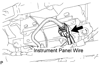
| 11. CONNECT INSTRUMENT PANEL WIRE ASSEMBLY |
Connect the connector (yellow colored one).
 |
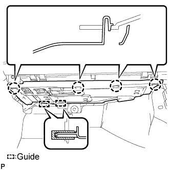
| 12. INSTALL NO. 1 DEFROSTER NOZZLE GARNISH |
Connect each connector.
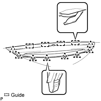 |
Engage the 4 guides.
Engage the 8 clips and install the No. 1 defroster nozzle garnish.
| 13. INSTALL FRONT NO. 2 SPEAKER ASSEMBLY (for LH Side) |
Connect the connector.
Install the front No. 2 speaker assembly with the 2 bolts.
 |
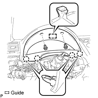
| 14. INSTALL INSTRUMENT PANEL NO. 1 SPEAKER PANEL SUB-ASSEMBLY |
Engage the 2 guides.
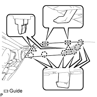 |
Engage the 6 claws and the 2 clips to install the instrument panel No. 1 speaker panel sub-assembly.
| 15. INSTALL INSTRUMENT PANEL NO. 1 REGISTER ASSEMBLY |
Engage the 4 clips and install the instrument panel No. 1 register assembly.
 |
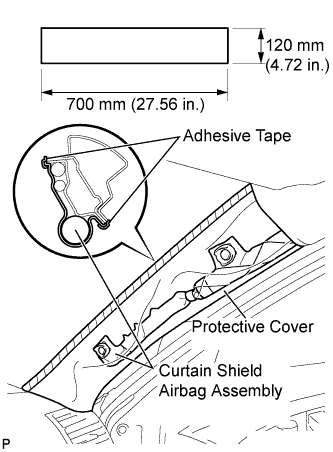
| 16. INSTALL FRONT PILLAR GARNISH LH |
Remove the protective cover.
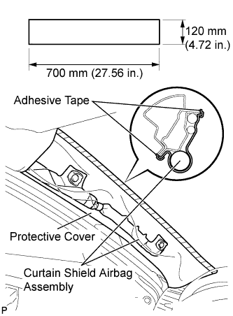 |
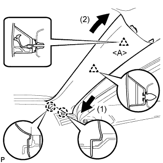
Install a new clip <A> on the front pillar garnish LH.
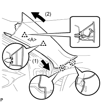 |
Engage the 2 claws and 2 clips, then install the front pillar garnish LH.
| 17. INSTALL FRONT NO. 2 SPEAKER ASSEMBLY (for RH Side) |
- HINT:
- Use the same procedures for the RH side and the LH side (CAMRY_ACV40 RM0000026JQ00LX_01_0001.html).
| 18. INSTALL INSTRUMENT PANEL NO. 2 SPEAKER PANEL SUB-ASSEMBLY |
Engage the 2 guides.
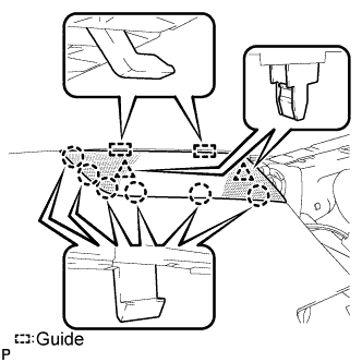 |
Engage the 6 claws and the 2 clips to install the instrument panel No. 2 speaker panel sub-assembly.
| 19. INSTALL INSTRUMENT PANEL NO. 3 REGISTER ASSEMBLY |
Engage the 4 clips and install the instrument panel No. 3 register assembly.
 |
| 20. INSTALL FRONT PILLAR GARNISH RH |
Remove the protective cover.
 |
Install a new clip <A> on the front pillar garnish RH.
 |
Engage the 2 claws and 2 clips, then install the front pillar garnish RH.
| 21. INSTALL NO. 1 CONSOLE BOX INSERT FRONT |
Engage the clip.
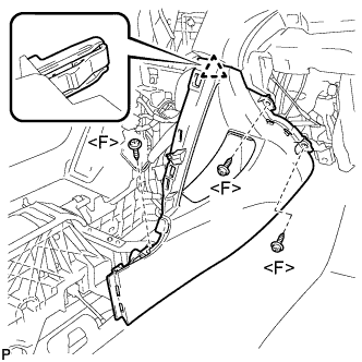 |
Install the No. 1 console box insert front with the 3 screws <F>.
| 22. INSTALL NO. 2 CONSOLE BOX INSERT FRONT |
Engage the clip.
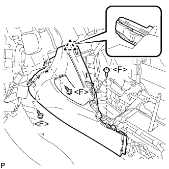 |
Install the No. 2 console box insert front with the 3 screws <F>.
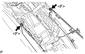
| 23. INSTALL CONSOLE BOX ASSEMBLY |
Install the 2 screws <F>.
 |
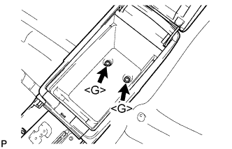
Install the console box assembly with the 2 bolts <G>.
 |
| 24. INSTALL CONSOLE BOX CARPET |
Install the console box carpet.
 |
| 25. INSTALL CONSOLE BOX POCKET |
Install the console box pocket.
| 26. INSTALL RADIO TUNER OPENING COVER WITH HEATER CONTROL PANEL ASSEMBLY (w/o Radio Receiver) |
Connect the connector.
Engage the 6 clips.
 |
Install the radio tuner opening cover with heater control panel assembly with the 4 bolts <N>.
| 27. INSTALL RADIO RECEIVER WITH HEATER CONTROL PANEL ASSEMBLY (w/ Radio Receiver) |
Connect each connector.
 |
Engage the 4 clips.
Install the radio receiver with heater control panel assembly with the 4 bolts.
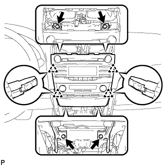
| 28. INSTALL INSTRUMENT PANEL NO. 2 REGISTER ASSEMBLY |
Connect the connector.
Engage the 7 clips and install the instrument panel No. 2 register assembly.
 |
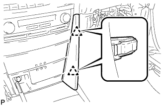
| 29. INSTALL LOWER INSTRUMENT CLUSTER FINISH PANEL CENTER SUB-ASSEMBLY |
Connect each connector.
Engage the 2 claws and 2 clips.
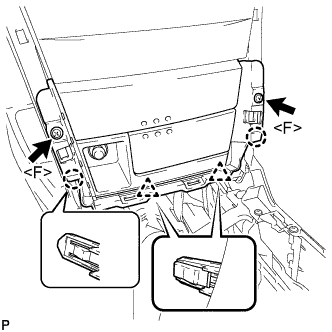 |
Install the lower instrument cluster finish panel center sub-assembly with the 2 screws <F>.
| 30. INSTALL UPPER CONSOLE REAR PANEL SUB-ASSEMBLY (for Automatic Transaxle) |
Connect the connector and engage the clamp.
 |
Engage the 3 claws and 5 clips to install the upper console rear panel sub-assembly.
| 31. INSTALL UPPER CONSOLE REAR PANEL SUB-ASSEMBLY (for Manual Transaxle) |
Engage the 3 claws and 5 clips to install the upper console rear panel sub-assembly.
 |
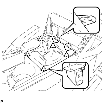
| 32. INSTALL FLOOR SHIFT POSITION INDICATOR HOUSING SUB-ASSEMBLY (for Automatic Transaxle) |
with Seat Heater System:
Connect each connector.
Engage the 6 claws and the 3 clips to install the floor shift position indicator housing sub-assembly.
 |
| 33. INSTALL UPPER CONSOLE PANEL (for Manual Transaxle) |
Engage the 2 claws and the 5 clips to install the upper console panel as shown in the illustration.
 |
| 34. INSTALL NO. 2 INSTRUMENT CLUSTER FINISH PANEL GARNISH |
Engage the 2 clips and install the No. 2 instrument cluster finish panel garnish.
 |
| 35. INSTALL NO. 1 INSTRUMENT CLUSTER FINISH PANEL GARNISH |
Engage the 2 clips and install the No. 1 instrument cluster finish panel garnish.
 |
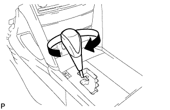
| 36. INSTALL SHIFT LEVER KNOB SUB-ASSEMBLY (for Automatic Transaxle) |
Install the shift lever knob sub-assembly.
 |
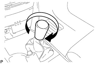
| 37. INSTALL SHIFT LEVER KNOB SUB-ASSEMBLY (for Manual Transaxle) |
Install the shift lever knob sub-assembly.
 |
| 38. INSTALL LOWER INSTRUMENT PANEL SUB-ASSEMBLY |
Engage the 3 claws and 3 clips.
 |
Install the 4 screws <B>.
Install the lower instrument panel sub-assembly with the bolt <A>.
| 39. INSTALL INSTRUMENT PANEL NO. 2 UNDER COVER SUB-ASSEMBLY |
Engage the 4 claws and 2 guides and install the instrument panel No. 2 under cover.
 |
| 40. INSTALL COWL SIDE TRIM SUB-ASSEMBLY RH |
- HINT:
- Use the same procedures for the RH side and the LH side.
| 41. INSTALL FRONT DOOR SCUFF PLATE RH |
- HINT:
- Use the same procedures for the RH side and the LH side.
| 42. INSTALL COMBINATION METER ASSEMBLY |
Connect each connector.
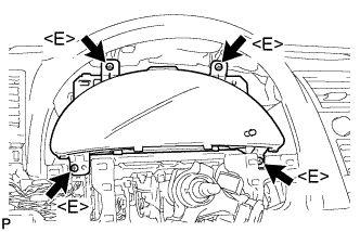 |
Install the combination meter assembly with the 4 screws <E>.
| 43. INSTALL INSTRUMENT CLUSTER FINISH PANEL NO.1 |
Engage the guide and the 4 claws.
 |
Install the instrument cluster finish panel with the 2 clips.
| 44. INSTALL LOWER INSTRUMENT PANEL FINISH PANEL |
Engage the 2 claws and 2 clips to install the lower instrument panel finish panel.
 |
| 45. INSTALL NO. 1 INSTRUMENT PANEL SUB-ASSEMBLY |
Connect each connector.
Engage the 3 claws and 2 clips to install the No. 1 instrument panel sub-assembly.
 |
| 46. INSTALL TURN SIGNAL SWITCH ASSEMBLY WITH SPIRAL CABLE SUB-ASSEMBLY |
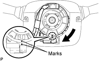
| 47. ADJUST SPIRAL CABLE SUB-ASSEMBLY |
Check that the ignition switch is off.
Check that the battery negative (-) cable is disconnected.
- CAUTION:
- Wait for 90 seconds after disconnecting the cable to prevent airbag deployment.
Rotate the spiral cable counterclockwise slowly by hand until it feels firm.
- NOTICE:
- Do not turn the spiral cable by the airbag wire harness.
 |
Rotate the spiral cable clockwise approximately 2.5 turns to align the marks.
- NOTICE:
- Do not turn the spiral cable by the airbag wire harness.
- HINT:
- The spiral cable will rotate approximately 2.5 turns to both the left and right from the center.
 |
| 48. INSTALL STEERING COLUMN COVER |
Engage the claw and install the upper steering column cover.
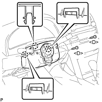 |
Engage the 2 claws and install the lower steering column cover.
Install the steering column cover with the 2 screws <D>.
- Torque:
- 2.0 N*m{20 kgf*cm, 18 in.*lbf}
| 49. INSTALL LOWER INSTRUMENT PANEL FINISH PANEL LH |
Install the air hose and connect the connector.
 |
Engage the 2 claws and the DLC3.
Engage the claw and the 4 clips.
Instal the lower instrument panel finish panel LH with the screw <B> and bolt <A>.
| 50. INSTALL COWL SIDE TRIM SUB-ASSEMBLY LH |
Engage the 2 clips.
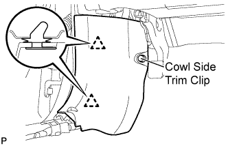 |
Install the cowl side trim sub-assembly LH with the cowl side trim clip.
| 51. INSTALL FRONT DOOR SCUFF PLATE LH |
Engage the 7 claws and 3 clips, then install the front door scuff plate LH.
 |
| 52. INSTALL STEERING WHEEL ASSEMBLY |
Align the matchmarks on the steering wheel assembly and steering main shaft.
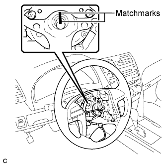 |
Install the steering wheel assembly set nut.
- Torque:
- 50 N*m{510 kgf*cm, 37 ft.*lbf}
Connect the connectors to the spiral cable sub-assembly.
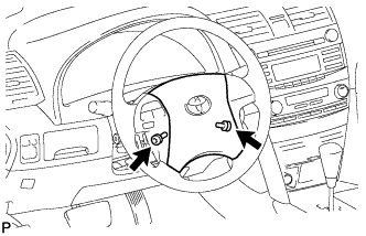
| 53. INSTALL STEERING PAD |
Check that the ignition switch is off.
Check that the battery negative (-) terminal is disconnected.
- CAUTION:
- Wait for 90 seconds after disconnecting the cable to prevent airbag deployment.
Support the steering pad with one hand.
 |
Connect the 2 airbag connectors to the steering pad.
- NOTICE:
- When handling the airbag connector, take care not to damage the airbag wire harness.
Connect the horn connector to the steering pad.
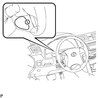
Confirm that the circumference groove of the "TORX" screw fits in the screw case, and place the steering pad onto the steering wheel assembly.
Using a "TORX" socket (T30), tighten the 2 "TORX" screws.
- Torque:
- 8.8 N*m{90 kgf*cm, 78 in.*lbf}
 |
| 54. INSTALL LOWER NO. 3 STEERING WHEEL COVER |
Engage the claw and install the No. 3 lower steering wheel cover.
 |
| 55. INSTALL LOWER NO. 2 STEERING WHEEL COVER |
Engage the claw and install the No. 2 lower steering wheel cover.
 |
| 56. INSTALL HEATER WATER HOSE INLET |
Install the water hose and attach the clip.
 |
| 57. INSTALL HEATER WATER HOSE OUTLET |
Use the same procedures described for the heater inlet water hose.
| 58. INSTALL AIR CONDITIONING TUBE AND ACCESSORY |
Remove the attached vinyl tape from the tube.
Sufficiently apply compressor oil to a new O-ring and fitting surface of the air conditioning tube assembly.
- Compressor oil:
- ND-OIL 8 or equivalent
Install the O-ring on the air conditioning tube and accessory.
Install the air conditioner tube and accessory.
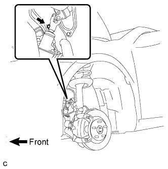
| 59. INSTALL SUCTION HOSE SUB-ASSEMBLY |
Remove the attached vinyl tape from the hose.
Sufficiently apply compressor oil to a new O-ring and the fitting surface of the suction hose sub-assembly.
- Compressor oil:
- ND-OIL 8 or equivalent
Install the O-ring on the suction hose sub-assembly.
Move the hook connector in the direction indicated by the arrow in the illustration.
 |
Insert the pipe joint into the fitting hole securely and tighten the bolt.
- Torque:
- 9.8 N*m{100 kgf*cm, 87 in.*lbf}
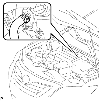
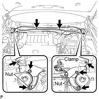
| 60. INSTALL COWL TOP OUTER FRONT PANEL SUB-ASSEMBLY |
Install the cowl top outer front panel sub-assembly with the 4 nuts, the 4 bolts and the clamp.
- Torque:
- Nut:
- 85 N*m{867 kgf*cm, 63 ft.*lbf}
 |
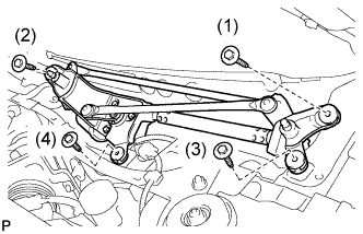
| 61. INSTALL WINDSHIELD WIPER MOTOR AND LINK ASSEMBLY |
Install the windshield wiper motor and link assembly with the 4 bolts.
- Torque:
- 7.5 N*m{77 kgf*cm, 66 in.*lbf}
- NOTICE:
- Tighten the bolts in the order shown in the illustration.
 |
Connect the connector.
 |
| 62. INSTALL COWL TOP VENTILATOR LOUVER SUB-ASSEMBLY |
Engage the 4 claws and install the cowl top ventilator louver sub-assembly.
 |
Install the 2 clips.
| 63. INSTALL FRONT FENDER TO COWL SIDE SEAL RH |
Engage the claw and install the front fender to cowl side seal RH.
 |
| 64. INSTALL FRONT FENDER TO COWL SIDE SEAL LH |
Engage the claw and install the front fender to cowl side seal LH.
 |
| 65. INSTALL FRONT WIPER ARM AND BLADE ASSEMBLY LH |
Operate the wiper and stop the windshield wiper motor at the automatic stop position.
Clean the wiper arm serrations.
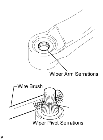 |
When reinstalling:
Clean the wiper pivot serrations with a wire brush.
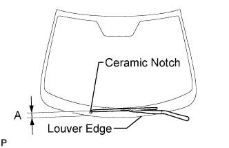
Install the front wiper arm and blade assembly LH with the nut to the position shown in the illustration.
- Torque:
- 20 N*m{204 kgf*cm, 15 ft.*lbf}
- HINT:
- Hold the arm hinge by hand to fasten the nut.
Area Measurement A 37 to 52 mm (1.46 to 2.05 in.)
 |
| 66. INSTALL FRONT WIPER ARM AND BLADE ASSEMBLY RH |
Operate the wiper and stop the windshield wiper motor at the automatic stop position.
Clean the wiper arm serrations.
|
When reinstalling:
Clean the wiper pivot serrations with a wire brush.
Install the front wiper arm and blade assembly RH with the nut to the position shown in the illustration.
- Torque:
- 20 N*m{204 kgf*cm, 15 ft.*lbf}
- HINT:
- Hold the arm hinge by hand to fasten the nut.
Area Measurement A 23 to 38 mm (0.90 to 1.49 in.)
 |
Operate the front wipers while spraying washer fluid on the windshield glass. Make sure that the front wipers function properly and the wipers do not come into contact with the vehicle body.
| 67. CONNECT NEGATIVE BATTERY TERMINAL |
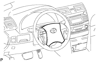
| 68. INSPECT STEERING PAD |
With the steering pad installed on the vehicle, perform a visual check. If there are any defects as mentioned below, replace the steering pad with a new one:
- Cuts, minute cracks or marked discoloration on the steering pad top surface or in the grooved portion.
- Cuts, minute cracks or marked discoloration on the steering pad top surface or in the grooved portion.
 |
Make sure that the horn sounds.
- HINT:
- If the horn does not sound, inspect the horn system (CAMRY_ACV40 RM0000016F501NX.html).
| 69. INSPECT SRS WARNING LIGHT |
| 70. ADD ENGINE COOLANT (for 2AZ-FE) |
Close the radiator drain cock plug and 2 cylinder block drain cock plugs.
- Torque:
- 13 N*m{130 kgf*cm, 9 ft.*lbf} for cylinder block drain cock plug
Slowly fill the radiator with TOYOTA Super Long Life Coolant (SLLC).
- Specified capacity:
- 6.2 liters (6.6 US qts, 5.5 lmp. qts)
- HINT:
- TOYOTA vehicles are filled with TOYOTA SLLC at the factory. In order to avoid damage to the engine cooling system and other technical problems, only use TOYOTA SLLC or similar high quality ethylene glycol based non-silicate, non-amine, non-nitrite, non-borate coolant with long-life hybrid organic acid technology (coolant with long-life hybrid organic acid technology consists of a combination of low phosphates and organic acids).
- Contact your TOYOTA dealer for further details.
Slowly pour coolant into the radiator reservoir tank until it reaches the FULL line.
Press the inlet and outlet radiator hoses several times by hand, and then check the level of the coolant.
If the coolant level is low, add coolant.
Install the radiator cap sub-assembly and reservoir tank cap.
Start the engine, and warm it up.
- HINT:
- Adjust the air conditioner set temperature to MAX (HOT).
Stop the engine, and wait until the engine coolant cools down.
Add engine coolant to the FULL line on the radiator reservoir.
| 71. ADD ENGINE COOLANT (for 2GR-FE) |
Close the radiator drain cock plug and 2 cylinder block drain cock plugs.
- Torque:
- 13 N*m{130 kgf*cm, 9 ft.*lbf} for cylinder block drain cock plug
Slowly fill the radiator with TOYOTA Super Long Life Coolant (SLLC).
- Specified capacity:
- 9.0 liters (9.5 US qts, 7.9 lmp. qts)
- HINT:
- TOYOTA vehicles are filled with TOYOTA SLLC at the factory. In order to avoid damage to the engine cooling system and other technical problems, only use TOYOTA SLLC or similar high quality ethylene glycol based non-silicate, non-amine, non-nitrite, non-borate coolant with long-life hybrid organic acid technology (coolant with long-life hybrid organic acid technology consists of a combination of low phosphates and organic acids).
- Contact your TOYOTA dealer for further details.
Slowly pour coolant into the radiator reservoir tank until it reaches the FULL line.
Press the inlet and outlet radiator hoses several times by hand, and then check the level of the coolant.
If the coolant level is low, add coolant.
Install the radiator cap sub-assembly and reservoir tank cap.
Start the engine, and warm it up.
- HINT:
- Adjust the air conditioner set temperature to MAX (HOT).
Stop the engine, and wait until the engine coolant cools down.
Add engine coolant to the FULL line on the radiator reservoir.
| 72. CHECK FOR ENGINE COOLANT LEAKS |
| 73. CHARGE WITH REFRIGERANT |
Perform vacuum purging using a vacuum pump.
Charge with refrigerant HFC-134a (R134a).

- Standard:
- 450 to 550 g (15.9 to 19.4 oz.)
- SST
- 07110-58060(07117-58060,07117-58070,07117-58080,07117-58090,07117-78050,07117-88060,07117-88070,07117-88080)
- NOTICE:
- Do not turn the A/C on before charging with refrigerant. Doing so will cause the cooler compressor to work without refrigerant, resulting in overheating of the cooler compressor.
- Approximately 100 g (3.53 oz.) of refrigerant may need to be charged after bubbles disappear.
The refrigerant amount should be checked by quantity, not with the sight glass.
- HINT:
- Ensure that sufficient refrigerant is available to recharge the system when using a refrigerant recovery unit. Refrigerant recovery units are not always able to recover 100 % of the refrigerant from an A/C system.
| 74. WARM UP ENGINE |
Keep the A/C switch on for at least 2 minutes to warm up the compressor.
- NOTICE:
- Be sure to warm up the compressor when turning the A/C on after removing and installing the cooler refrigerant lines (including the compressor), to prevent damage to the compressor.
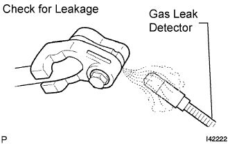
| 75. CHECK FOR REFRIGERANT LEAKS |
After recharging with refrigerant gas, check for leakage of refrigerant gas using a halogen leak detector.
Carry out the test under the following conditions:
- IG OFF
- Secure good ventilation (the gas leak detector may react to volatile gases which are not refrigerant, such as evaporated gasoline and exhaust gas).
- Repeat the test 2 or 3 times.
- Make sure that there is some refrigerant remaining in the refrigeration system.
When the compressor is off: approx. 392 to 588 kPa (4 to 6 kgf/cm2, 57 to 85 psi)
- IG OFF
Using a gas leak detector, check for leakage from the refrigerant lines.
 |
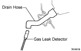
Bring the gas leak detector close to the drain hose with the detector's power off, and then turn the detector on.
- HINT:
- After the blower motor has stopped, let the cooling unit stand for more than 15 minutes.
- Bring the gas leak detector sensor under the drain hose.
- When bringing the gas leak detector close to the drain hose, make sure that the gas leak detector does not react to volatile gases.
If it is not possible to avoid interference from volatile gases, the vehicle should be lifted up to allow testing.
 |
If a gas leak is not detected from the drain hose, remove the blower motor control from the cooling unit. Insert the gas leak detector sensor into the unit and perform the test.
Disconnect the pressure switch connector and leave it for approximately 20 minutes. Bring the gas leak detector close to the pressure switch and perform the test.