Engine Immobiliser System (W/O Entry And Start System) Ecu Power Source Circuit
DESCRIPTION
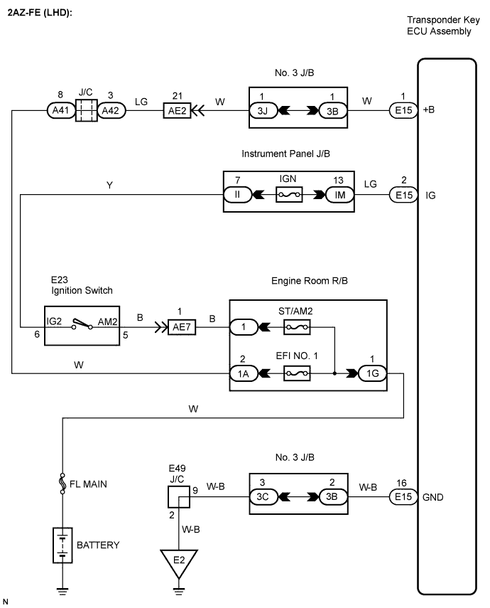
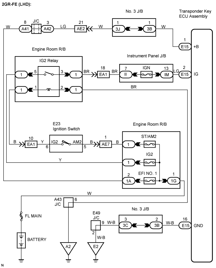
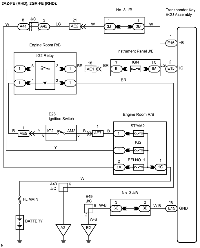
WIRING DIAGRAM
INSPECTION PROCEDURE
CHECK HARNESS AND CONNECTOR (TRANSPONDER KEY ECU - BATTERY)
CHECK HARNESS AND CONNECTOR (TRANSPONDER KEY ECU - BODY GROUND)
ENGINE IMMOBILISER SYSTEM (w/o Entry and Start System) - ECU Power Source Circuit |
DESCRIPTION
This circuit provides power to operate the transponder key ECU assembly.
WIRING DIAGRAM
INSPECTION PROCEDURE
- NOTICE:
- If the transponder key ECU assembly is replaced, register the key and ECU communication ID.
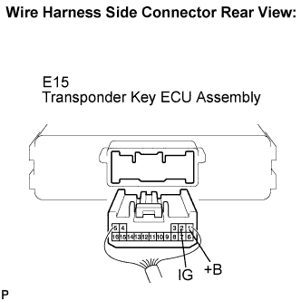
| 1.CHECK HARNESS AND CONNECTOR (TRANSPONDER KEY ECU - BATTERY) |
Disconnect the E15 ECU connector.
Measure the voltage according to the value(s) in the table below.
- Standard voltage:
Tester Connection
| Condition
| Specified Condition
|
E15-1 (+B) - Body ground
| Always
| 10 to 14 V
|
E15-2 (IG) - Body ground
| Ignition switch OFF
| Below 1 V
|
Ignition switch ON
| 10 to 14 V
|
| | REPAIR OR REPLACE HARNESS OR CONNECTOR, OR REPLACE FUSE |
|
|
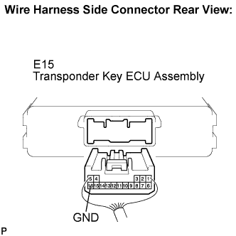
| 2.CHECK HARNESS AND CONNECTOR (TRANSPONDER KEY ECU - BODY GROUND) |
Measure the resistance according to the value(s) in the table below.
- Standard resistance:
Tester Connection
| Condition
| Specified Condition
|
E15-16 (GND) - Body ground
| Always
| Below 1 Ω
|
| | REPAIR OR REPLACE HARNESS OR CONNECTOR |
|
|
| OK |
|
|
|
| PROCEED TO NEXT CIRCUIT INSPECTION SHOWN IN PROBLEM SYMPTOMS TABLE |
|