Ignition Coil -- Installation |
| 1. INSTALL IGNITION COIL ASSEMBLY |
Install the 6 ignition coils with the 6 bolts.
- Torque:
- 10 N*m{102 kgf*cm, 10 ft.*lbf}
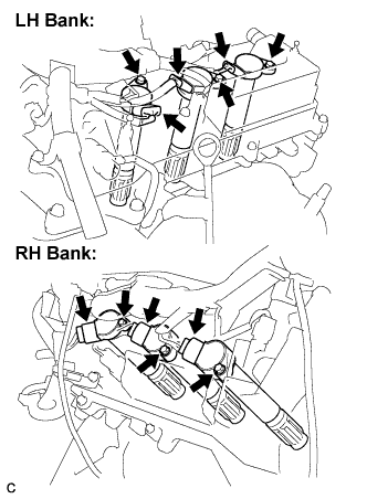 |
Connect the 6 ignition coil connectors.
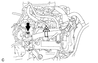
| 2. INSTALL NO. 1 SURGE TANK STAY |
- NOTICE:
- DO NOT apply oil to the bolt listed below:
| Tightening Parts |
| No. 1 Surge tank stay and Cylinder head cover |
Install the No. 1 surge tank stay with the bolt.
- Torque:
- 21 N*m{214 kgf*cm, 15 ft.*lbf}
 |
Install the bolt and clamp.
- Torque:
- 7.0 N*m{71 kgf*cm, 62 in.*lbf}
 |
| 3. INSTALL INTAKE AIR SURGE TANK ASSEMBLY |
- NOTICE:
- DO NOT apply oil to the bolts listed below:
| Tightening Parts | ||
| Surge Tank and Intake Manifold | ||
| No. 1 Surge Tank Stay and Surge Tank | ||
| Throttle Body Bracket and Surge Tank |
Install a new gasket to the intake air surge tank.
 |
Using a 5 mm hexagon socket wrench, install the 4 bolts.
- Torque:
- 18 N*m{184 kgf*cm, 13 ft.*lbf}
Install the intake air surge tank with the 2 nuts and 2 bolts.
- Torque:
- Nut:
- 16 N*m{163 kgf*cm, 12 ft.*lbf}
- Bolt:
- 21 N*m{214 kgf*cm, 15 ft.*lbf}
Connect the connector.
 |
Install the vacuum hose clamp with the bolt.
- Torque:
- 5.4 N*m{55 kgf*cm, 48 in.*lbf}
 |
Connect the union to check valve hose.
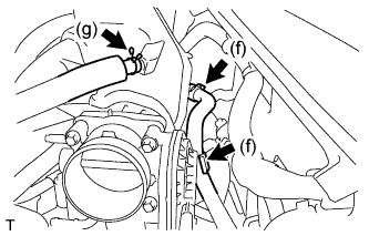 |
Connect the No. 1 ventilation hose.
Install the clamp and connect the throttle with motor body assembly connector.
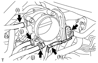 |
Connect the vapor feed hose.
Connect the 2 water by-pass hoses to the throttle with motor body assembly.
| 4. INSTALL AIR CLEANER CAP SUB-ASSEMBLY |
Install the air cleaner cap sub-assembly, and connect the 3 bands.
 |
Connect the mass air flow meter connector (*1).
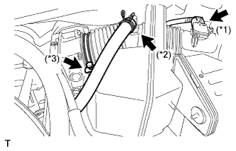 |
Connect the No. 2 ventilation hose (*2).
Connect the hose band (*3).
Connect the 3 vacuum hoses.
 |
| 5. CONNECT CABLE TO NEGATIVE BATTERY TERMINAL |
- Torque:
- 6.9 N*m{70 kgf*cm, 61 in.*lbf}
| 6. ADD ENGINE COOLANT |
Close the radiator drain cock plug and 2 cylinder block drain cock plugs.
- Torque:
- 13 N*m{130 kgf*cm, 9 ft.*lbf} for cylinder block drain cock plug
Slowly fill the radiator with TOYOTA Super Long Life Coolant (SLLC).
- Specified capacity:
- 9.0 liters (9.5 US qts, 7.9 lmp. qts)
- HINT:
- TOYOTA vehicles are filled with TOYOTA SLLC at the factory. In order to avoid damage to the engine cooling system and other technical problems, only use TOYOTA SLLC or similar high quality ethylene glycol based non-silicate, non-amine, non-nitrite, non-borate coolant with long-life hybrid organic acid technology (coolant with long-life hybrid organic acid technology consists of a combination of low phosphates and organic acids).
- Contact your TOYOTA dealer for further details.
Slowly pour coolant into the radiator reservoir tank until it reaches the FULL line.
Press the inlet and outlet radiator hoses several times by hand, and then check the level of the coolant.
If the coolant level is low, add coolant.
Install the radiator cap sub-assembly and reservoir tank cap.
Start the engine, and warm it up.
- HINT:
- Adjust the air conditioner set temperature to MAX (HOT).
Stop the engine, and wait until the engine coolant cools down.
Add engine coolant to the FULL line on the radiator reservoir.
| 7. CHECK FOR ENGINE COOLANT LEAKS |
- CAUTION:
- Do not remove the radiator cap while the engine and radiator are still hot. Pressurized, hot engine coolant and steam may be released and cause serious burns.
- NOTICE:
- Before performing each inspection, turn the A/C switch OFF.
Fill the radiator with coolant and attach a radiator cap tester.
 |
Warm up the engine.
Using a radiator cap tester, increase the pressure inside the radiator to 118 kPa (1.2 kgf*cm, 17 psi), and check that the pressure does not drop.
If the pressure drops, check the hoses, radiator and water pump for leaks. If no external leaks are found, check the heater core, cylinder block and cylinder head.
| 8. INSTALL COWL TOP PANEL OUTER SUB-ASSEMBLY |
Install the cowl top panel outer sub-assembly with the 4 bolts and 4 nuts.
- Torque:
- Bolt:
- 5.0 N*m{51 kgf*cm, 44 in.*lbf}
- Nut:
- 85 N*m{867 kgf*cm, 63 ft.*lbf}
 |
| 9. INSTALL WINDSHIELD WIPER LINK ASSEMBLY |
| 10. INSTALL V-BANK COVER SUB-ASSEMBLY |
Engage the 3 retainers to install the V-bank cover.
 |